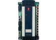
- Model: 1TGE120011R1001 (MNS iS Control 70)
- Brand: ABB (Germany/Switzerland)
- Series: MNS iS Smart Low Voltage Switchgear
- Core Function: Integrated motor control and protection unit for MNS iS systems (New Surplus)
- Product Type: Motor Management / Control Module
- Key Specs: Microprocessor-based | Real-time monitoring | MLink integration
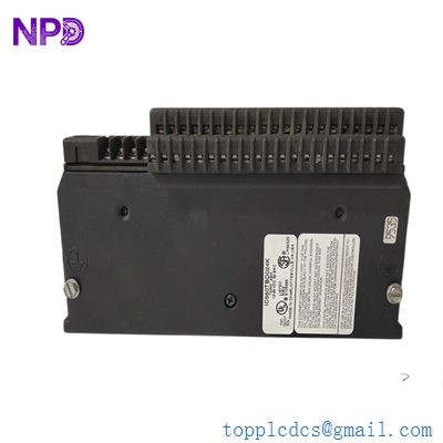
GE IC660TBD024K
Key Technical Specifications
- Rated Voltage: 24 V DC (Internal supply from MNS iS bus)
- Communication Interface: Internal high-speed bus to MLink (TCP/IP or Profibus via Gateway)
- Control Functions: Start/Stop, Forward/Reverse, Star-Delta, Soft-starter control
- Protection Features: Thermal overload, Phase failure, Stall, Earth fault, Underload
- Monitoring: Current (per phase), Voltage, Power factor, Energy consumption
- I/O Capability: Digital inputs for local control; Relay outputs for contactor drive
- Installation: Drawer-integrated (specifically designed for MNS iS switchboard drawers)
- Status Indication: Front-panel LEDs for Power, Run, and Fault diagnostics
- Configuration: Via MNS iS Engineer tool (Parameterization)
Installation & Configuration Guide
Phase 1: Pre-Installation
Estimated time: 10 minutes
⚠️ Safety Protocol:
- Ensure the MNS iS drawer is in the “Withdrawn” or “Test” position before attempting module replacement.
- Confirm the 24 V DC control power is isolated.
- Verify that the current transformer (CT) secondary circuit is shorted or the module is fully seated before applying primary power (to prevent high voltage transients).
Preparation:
- Anti-static (ESD) gloves.
- Laptop with MNS iS Engineer software (if address re-assignment is needed).
- Check the firmware revision on the side label of the 1TGE120011R1001.
Phase 2: Removal
Estimated time: 5 minutes
- Disconnect Wiring: If the module uses pluggable terminal blocks, gently unplug them. If hard-wired, label each wire according to the terminal numbering.
- Release Clips: Locate the plastic retaining clips on the module housing.
- Slide Out: Pull the module straight out from the internal mounting rail inside the drawer. Be careful not to strain the internal communication ribbon cable connecting to the drawer backplane.
Phase 3: Installation
Estimated time: 10 minutes
- Mounting: Snap the new 1TGE120011R1001 onto the internal rail.
- Connection: Re-attach the internal bus cable. Ensure the connector is fully seated and the locking tabs are engaged.
- I/O Wiring: Plug the terminal blocks back into the module.
- Pro-tip: Ensure the CT wires are securely connected; a loose CT connection can cause the module to report “Phase Loss” or “CT Open” faults immediately upon startup.
Phase 4: Power-On & Testing
Estimated time: 20 minutes
- Move Drawer to Test: Shift the drawer to the “Test” position to apply control power without energizing the main motor bus.
- Check LEDs:
- Power (Green): Should be steady.
- Communication (Yellow): Should flicker, indicating data exchange with the MLink.
- Address Assignment: If the module does not automatically pick up the address from the backplane, use the MNS iS Engineer tool to assign the correct Node ID.
- Functional Test: Execute a “Local Start” from the drawer front panel and verify the main contactor closes. Check for any “Interlock” alarms on the system HMI.
Customer Cases & Industry Applications
Case 1: Petrochemical Plant Motor Control Upgrade
Situation: A major refinery was experiencing intermittent “Communication Lost” faults on several 110kW pump motors controlled by an aging MNS iS switchgear.
Task: The reliability of the cooling pumps was critical for plant safety. The plant needed to replace the Control 70 modules (1TGE120011R1001) that had suffered thermal degradation over 10 years of continuous operation.
Action: We supplied 4 units of New Surplus 1TGE120011R1001. Because these were New Surplus, they were from the same late-production batch, ensuring firmware consistency across the motor group.
Result: The swap was performed during a 48-hour maintenance window. The refinery reported a 100% resolution of communication errors and improved current monitoring accuracy. They saved approximately $8,000 per module compared to the “New Product” factory price.
Frequently Asked Questions (FAQ)
Q1: Is the 1TGE120011R1001 a direct replacement for older MNS iS Control modules? A: It depends on the generation. The Control 70 (1TGE120011R1001) is the standard for MNS iS systems. However, if you are replacing an even older “MNS iS Control” (non-70) unit, you may need to update the MLink configuration file to recognize the new hardware ID.
Q2: Does the module store the motor parameters? A: In an MNS iS system, parameters are usually pushed from the MLink to the Control module upon startup. However, it is a best practice to verify the settings using the Engineer tool after installation to ensure the thermal overload curves match your specific motor.
Q3: Why is my module showing a “Red” Fault LED immediately? A: This is often caused by an incorrect current range setting. If the Control 70 is configured for a 100A CT but detects 0A (or vice versa), it will trip. Check that the CT ratio in the software matches the physical CT installed in the drawer.
Q4: Can I buy this as a “Refurbished” unit? A: I strongly advise against refurbished units for motor protection. These modules contain sensitive current-sensing circuitry. Refurbished units often have dried-out capacitors or stressed optocouplers that can fail under the heat of a switchgear cabinet. New Surplus is the only reliable way to ensure 10+ years of life.
Q5: What is the lead time if you run out of stock? A: As these are legacy components, factory lead times can exceed 16-20 weeks. We maintain a strategic buffer to provide 48-hour shipping for emergency “Motor Down” scenarios.