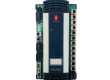
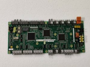
- Model: UFC760BE142 (3BHE004573R0142)
- Brand: ABB (Switzerland)
- Series: AC 800PEC / Power Electronics Series
- Core Function: High-speed inverter control and signal processing board (New Surplus)
- Product Type: Printed Circuit Board (PCB) / Control Unit
- Key Specs: Integrated FPGA/DSP | Fiber Optic Communication | Multi-channel I/O
3BHE004573R0142 UFC760BE142
Key Technical Specifications
- Processing Core: High-performance DSP for real-time motor control loops
- Communication: Multiple Fiber Optic (VME/PE-bus) ports for noise-immune data transfer
- Input Voltage: Typically 24 V DC internal supply from the backplane
- Interface: Integrated LVDS and high-speed serial links
- Compatibility: Primarily used in ACS6000 drives and UNITROL 6000 excitation systems
- Environmental: Conformal coating for protection against industrial pollutants
- Diagnostic Features: On-board LED matrix for real-time status and error codes
- Sampling Rate: Microsecond-level resolution for current and voltage sensing
Installation & Configuration Guide
Phase 1: Pre-Installation
Estimated time: 15 minutes
⚠️ Critical Warning:
- This board is the “brain” of high-power inverters. Ensure the DC Link is fully discharged (verify with a high-voltage meter, < 50V) before opening the cabinet.
- Fiber Optics: Ensure the fiber optic tips are clean. Use specialized cleaning wipes; never touch the ends with bare fingers.
- ESD Protection: Use a grounded wrist strap. The FPGA on this board can be damaged by invisible static charges.
Preparation:
- Torx T20/T25 screwdrivers.
- Fiber optic cleaning kit.
- Anti-static bags for the old board.
Phase 2: Removal
Estimated time: 10 minutes
- Fiber Optic Labeling: Before disconnecting, label every fiber optic cable (e.g., TX1, RX1). Swapping these during re-installation will prevent the drive from starting.
- Disconnecting: Gently unplug the fiber optic connectors by squeezing the locking tabs. Remove any ribbon cables or auxiliary power connectors.
- Unmounting: Unscrew the captive screws or mounting bolts securing the UFC760BE142 to the subrack. Slide the board out carefully, avoiding contact with other components.
Phase 3: Installation
Estimated time: 15 minutes
- Alignment: Align the board with the card guide rails. Ensure the backplane connector is straight.
- Insertion: Slide the board in firmly until the connector is fully seated. Tighten the mounting screws to ensure a solid ground path.
- Reconnect Cables:
- Re-insert fiber optics until they “click.”
- Re-attach all ribbon cables, ensuring correct orientation (Pin 1).
- Visual Inspection: Check for any loose wires or tools left near the high-voltage busbars.
Phase 4: Power-On & Testing
Estimated time: 20 minutes
- Auxiliary Power Up: Apply control power (24 V) only. Do not apply high voltage (DC Link) yet.
- LED Verification: Observe the LED pattern. A healthy board typically shows a steady heartbeat or “Run” LED.
- Software/Firmware Check: Use the ABB DriveWindow or Control Builder software to verify that the board is detected and that the firmware version matches the rest of the system.
- Note: You may need to download the application software to the new board if it does not come pre-loaded.
- Final Commissioning: Perform a “pulse test” or ID run (if required) before returning the system to full load production.
Customer Cases & Industry Applications
Case 1: ACS6000 Drive Failure in a Mining Operation
Situation: A large mining facility in Australia experienced a trip on their main ventilation fan drive (ABB ACS6000). The diagnostic fault code pointed to a “Control Board Communication Error.”
Task: The ventilation system is safety-critical; without it, underground operations must stop. The local service provider quoted a 12-week lead time for a new UFC760BE142 board.
Action: We provided a New Surplus 3BHE004573R0142 board from our inventory. We assisted the client’s engineer in verifying that the revision (R0142) was compatible with their existing control software version.
Result: The board was flown in via express courier and installed within 72 hours. The drive was back in operation immediately after a firmware sync, saving the mine millions in lost production time.
Frequently Asked Questions (FAQ)
Q1: Can the UFC760BE142 replace older UFC760AE versions? A: Technically, no. While they belong to the same family, the “BE” and “AE” versions often have different FPGA logic or memory capacities. Replacing an “AE” with a “BE” usually requires a significant software update. Always stick to the exact part number for “Plug-and-Play” capability.
Q2: Does the board come with the application software pre-installed? A: Most New Surplus boards come with the Base System Firmware but not your specific application software (the logic that tells your specific drive how to behave). You will likely need to use DriveWindow to clone the software from your backup or the redundant controller.
Q3: What are the most common failure points on these boards? A: In my experience, failure is often caused by fiber optic transceiver degradation or overheating due to clogged cabinet filters. If your drive reports “Link Fail,” check the fiber cables first before replacing the entire board.
Q4: Is it safe to buy “New Surplus” for a safety-critical system? A: Yes, provided the source is verified. As a Spare Parts Manager, I ensure our UFC boards are kept in climate-controlled, ESD-safe environments. These boards do not have the same “aging” issues as electrolytic capacitors in power modules, making them very reliable even as surplus stock.
Q5: What is the significance of the R0142 suffix? A: The “R” number refers to the revision and hardware configuration. Small changes in the R-suffix can sometimes mean different I/O counts or internal voltage ratings. Always confirm the R-suffix matches your existing BOM (Bill of Materials).