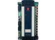
- Model: CI861 (3BSE058590R1)
- Brand: ABB (Sweden)
- Series: AC 800M / System 800xA
- Core Function: PROFIBUS DP/V1 Communication Interface (New Surplus)
- Product Type: Communication Module / Interface Module
- Key Specs: 12 Mbit/s Max Baud Rate | Supports Redundancy | Master or Slave
CI861 3BSE058590R1
Key Technical Specifications
- Protocol: PROFIBUS DP/V1 (Asynchronous and Synchronous)
- Connector: 9-pin D-sub (female)
- Data Rate: Auto-sensing up to 12 Mbit/s
- Isolation: Reinforced isolation from system power and CEX-bus
- Power Supply: 24 V DC (Supplied via the CEX-bus)
- Redundancy: Supported (Requires two CI861 modules and specific baseplate)
- Addressing: Soft-addressing via Control Builder M
- Diagnostics: Integrated LEDs for Run, Fault, and Traffic status
- Max Units: Up to 12 modules per AC 800M controller (dependent on CPU load)
Installation & Configuration Guide
Phase 1: Pre-Installation
Estimated time: 10 minutes
⚠️ Safety Protocol:
- Check the CEX-bus capacity. Adding a CI861 increases the 24 V load on the BC810 or PM8xx power supply.
- Confirm the Firmware Version. The CI861 firmware must be compatible with the AC 800M controller version (e.g., v5.1, v6.0).
- Ensure the controller is in a safe state if not using a redundant configuration.
Preparation:
- Small flathead screwdriver for the D-sub connector.
- Antistatic wrist strap.
- Check the PROFIBUS termination switches on the cable connectors.
Phase 2: Removal
Estimated time: 5 minutes
- Unplug PROFIBUS: Loosen the two screws on the 9-pin D-sub connector and pull it straight out.
- Release Module: Push the locking tabs (usually located at the top and bottom of the module housing).
- Slide Out: Gently pull the module forward, disconnecting it from the CEX-bus side connector.
Phase 3: Installation
Estimated time: 10 minutes
- Module Alignment: Align the module with the guide rails on the CEX-bus baseplate (or directly to the PM8xx if no other modules exist).
- Engagement: Push firmly until the module clicks into place and the side connector is fully seated.
- Cable Connection: Plug in the PROFIBUS D-sub connector.
- Pro-tip: Ensure the cable has proper strain relief; heavy PROFIBUS cables can damage the D-sub pins over time.
Phase 4: Power-On & Testing
Estimated time: 20 minutes
- Power Up: The module will initialize as the controller boots.
- LED Indicators:
- RUN (Green): Should be solid once the module is configured.
- FAULT (Red): If solid, indicates a hardware failure or firmware mismatch.
- Configuration:
- Open Control Builder M.
- Right-click the Hardware tree and “Insert” the CI861.
- Assign the PROFIBUS Station Address.
- Download: Perform a “Download and Go.” The module will restart and begin scanning slave devices.
Customer Cases & Industry Applications
Case 1: Chemical Plant Redundancy Upgrade
Situation: A chemical processing facility in Europe was running a single-channel PROFIBUS network on an AC 800M system. Frequent communication drops due to cable interference were causing “Safety Shutdowns.”
Task: The client decided to implement Module Redundancy for their PROFIBUS Master to increase uptime. They needed two identical CI861 modules immediately.
Action: We supplied two 3BSE058590R1 units from the same production batch to ensure identical hardware revisions. We also provided the technical specifications for the required redundancy baseplate.
Result: The plant successfully implemented the redundant PROFIBUS link. Since the upgrade, they have reported zero unplanned shutdowns related to fieldbus communication, saving an estimated $45,000 per month in lost production.
Frequently Asked Questions (FAQ)
Q1: What is the difference between CI854 and CI861? A: Both are PROFIBUS modules, but the CI861 is the newer, more robust version designed for the AC 800M “High Performance” range. The CI861 offers better processing power and is the standard recommendation for 800xA systems version 5.0 and above.
Q2: Does this module require a separate power supply? A: No. It draws power directly from the CEX-bus. However, you must ensure your PM8xx controller or BC810 Bus Extender has enough current capacity to support the additional 24 V load of the module.
Q3: Can I hot-swap the CI861? A: If you have a redundant pair, you can hot-swap the faulty module without stopping the controller. If it is a non-redundant standalone module, removing it will break the communication loop and likely trip your I/O—use caution.
Q4: Why is my “Fault” LED blinking? A: A blinking red LED usually indicates that the module is functional but hasn’t been configured by the CPU yet, or there is a configuration mismatch (e.g., you configured a CI861 in software but installed a CI854).
Q5: Are these modules “New” or “Refurbished”? A: We specialize in New Surplus. These are units that were never installed, kept in climate-controlled spare parts rooms. They offer the reliability of a new part at a lower price point and are much safer than “Refurbished” units which may have heat-stressed capacitors.