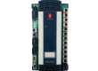
The ABB UAD149A0001, identified by the part number 3BHE014135R0001, is a high-reliability control module specifically engineered for ABB’s advanced excitation systems, most notably the UNITROL® 6000 and MEGATROL series. It serves as a critical interface and processing node that manages the magnetic field of synchronous machines, ensuring grid stability and voltage regulation for large-scale power generators.
1. Product Parameters and Technical Datasheet
The UAD149A0001 is built on a modular architecture designed for high-availability environments. It integrates high-speed digital logic with robust analog-to-digital conversion capabilities to monitor and adjust generator parameters in real-time.
Core Technical Specifications
| Parameter | Details |
| Model Designation | UAD149A0001 |
| Part Number | 3BHE014135R0001 |
| Processor Type | High-performance 32-bit Embedded RISC Processor |
| Supply Voltage | 24V DC (nominal), range 18V to 32V |
| Power Consumption | 20W to 35W (depending on active I/O load) |
| Communication Bus | AF 100 (Advant Fieldbus), High-speed Ethernet, RS-485 |
| Fiber Optic Ports | Integrated for high-speed synchronization and EMI immunity |
| Input Channels | Isolated Analog Inputs for Pt100, 4-20mA, and voltage sensing |
| Output Channels | Digital High-speed Gate Pulse Outputs for Thyristor bridges |
| Operating Temperature | -5°C to +70°C (Extended industrial range) |
| Protection Rating | IP20 (designed for subrack/cabinet mounting) |
Hardware Characteristics
- Galvanic Isolation: Every signal path is meticulously isolated to protect the control electronics from the high-voltage transients inherent in generator excitation circuits.
- FPGA Integration: The unit utilizes Field Programmable Gate Arrays (FPGAs) to handle the microsecond-level timing required for Pulse Width Modulation (PWM) and firing angle control of thyristor rectifiers.
- Redundancy Support: Specifically designed to operate in “Hot Standby” or “Parallel Redundant” modes. When paired with a second unit, the UAD149A0001 supports bumpless transfer, ensuring that a single module failure does not trip the generator.
2. Country of Origin
The UAD149A0001 is manufactured in Switzerland. ABB’s Center of Excellence for Power Electronics and Excitation Systems is located in Turgi, where these controllers undergo rigorous “Burn-in” testing to simulate the harsh electrical environments of power plants before being shipped globally.
3. Application Areas
This controller is a specialized device used in the most critical infrastructure sectors. It is not a general-purpose PLC; it is a dedicated power electronics controller.
Power Generation
- Hydroelectric Plants: Managing the excitation of large vertical and horizontal hydro-generators where rapid response to grid frequency fluctuations is required.
- Nuclear & Thermal Power: Providing steady-state voltage regulation and robust “Black Start” capabilities for massive synchronous generators.
- Gas Turbine Control: Integrated with the turbine control system to provide high-speed reactive power compensation.
Heavy Industry
- Synchronous Motors: Controlling the excitation of large motors used in the mining industry (grinding mills) and the marine sector (propulsion motors for LNG carriers).
- Static Var Compensators (SVC): Employed in grid-tie stations to regulate line voltage by managing reactive power flow.
4. Product Usage Instructions
Installation Guidelines
- Mechanical Mounting: The UAD149A0001 must be installed in a standard ABB subrack. Ensure that the module is locked using the top and bottom ejection levers. Improper seating can result in intermittent communication on the backplane bus.
- ESD Protection: Always handle the unit using an anti-static wrist strap. The 3BHE014135R0001 contains highly sensitive surface-mount devices that can be damaged by invisible static discharges.
- Cooling: Ensure the cabinet’s forced-air cooling system is operational. The unit dissipates heat through its aluminum front panel; obstructing airflow can lead to thermal throttling of the processor.
Wiring and Connectivity
- Fiber Optics: Use only ABB-certified fiber optic cables for the link between the UAD149A0001 and the I/O stations. Ensure the “Bending Radius” of the cables is at least 30mm to prevent signal loss.
- Power Supply: Use redundant 24V DC feeders. It is recommended to use Diode Redundancy Modules (e.g., ABB CP-RUD) to ensure the controller stays powered if one DC source fails.
Configuration and Commissioning
- Software Tool: Configuration is performed via the ABB Control Builder or UNITROL Toolset.
- Parameter Loading: Before putting the unit into “Auto” mode, parameters for the PSS (Power System Stabilizer) and the AVR (Automatic Voltage Regulator) must be calculated based on the generator’s open-circuit and short-circuit characteristics.
5. Product Related News
Lifecycle and Sustainability
In recent years, the UAD149A0001 has been the focus of ABB’s “Life Cycle Management” strategy. As part of the transition to digital power plants, ABB has released firmware updates for the 3BHE014135R0001 that allow it to interface more effectively with the ABB Ability™ cloud platform. This allows plant operators to monitor the “health” of the excitation system remotely and predict potential failures in the thyristor bridges.
Cybersecurity Enhancements
With the rise of threats to national power grids, ABB has issued specialized security patches for the UAD149 communication stack. These updates provide encrypted communication over the Ethernet service port, preventing unauthorized access to the excitation setpoints.
Modernization Projects
The 3BHE014135R0001 is currently the “go-to” replacement module for aging UNITROL 5000 systems. ABB news reports indicate a surge in retrofit projects in North America and Southeast Asia, where older excitation controllers are being replaced by the UAD149A0001 to improve grid compliance and response times for renewable energy integration.
6. Technical Maintenance Q&A
Q: What is the significance of the “Status” LED blinking Yellow? A: A blinking yellow LED typically indicates that the module is in “Service Mode” or is waiting for a configuration download. If this occurs during normal operation, it signifies a non-critical hardware warning, such as a redundant link failure.
Q: Can the UAD149A0001 be replaced while the generator is running? A: Only if the system is configured in a Dual Channel (Redundant) architecture. In a single-channel setup, removing the module will result in a “Loss of Excitation” trip, which will disconnect the generator from the grid. In redundant systems, the “Channel Select” logic must be verified before a “Hot Swap” is attempted.
Q: How often should the internal backup battery be checked? A: The UAD149A0001 uses high-reliability flash memory for its core logic, but it may rely on a battery for real-time clock (RTC) data. It is recommended to check the battery voltage during every biennial (2-year) maintenance shutdown.
Q: What is the maximum distance for the fiber optic link? A: For standard plastic optical fiber (POF), the limit is typically 15-20 meters. For distances up to 200 meters, Hard Clad Silica (HCS) fibers must be used with compatible transceiver settings.