- Model: Rolls-Royce CCN-11
- Brand: Rolls-Royce (marine & industrial control systems)
- Series: CanMan Controller Network Node
- Core Function: Controller Area Network (CAN) control node for distributed automation
- Type: Controller Network Interface Module
- Key Specs: CAN bus interface Redundant communication design Compact control processor
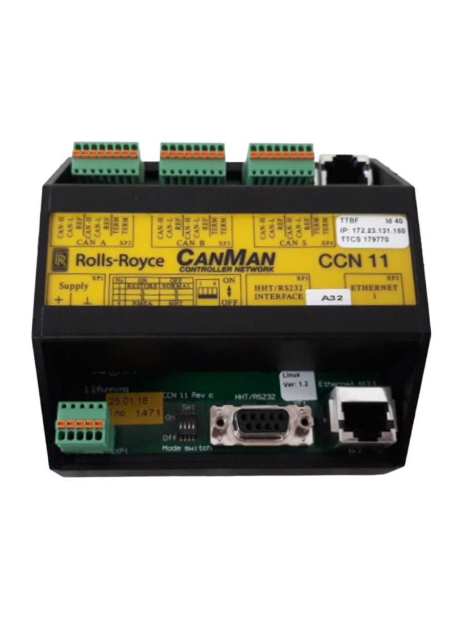
Rolls-Royce CCN-11
Key Technical Specifications
(General attributes based on CanMan architecture and available parts listings)
- Part Number / SKU: CCN-11 / 933252
- Controller Type: Distributed CAN network controller node
- Network Interface: Dual redundant CAN buses (A & B) for fault-tolerant messaging
- I/O Networking: CAN interface to SLIO and peripheral nodes
- Processor Class: Embedded control processor (typically microcontroller class)
- Memory: On-board program & parameter storage (EEPROM/Flash in typical CCN designs)
- Communication: Real-time CAN messaging with prioritized arbitration
- Redundancy: Supports parallel CAN channels for safety & reliability
- Operating Voltage: Logic and bus-powered (verify per system)
- Mounting: Backplane or module rack mount in automation system
- Environmental: Industrial / marine operation designs
Note: Exact processor, firmware version, and I/O configuration vary by build and application. Confirm specific OEM documentation for precise electrical and mechanical specifications.
Part 4: Installation & Configuration Guide
Phase 1: Preparation (≈10 minutes)
⚠️ Safety & Control Isolation
- Coordinate planned maintenance and set process to a safe state.
- Power down network and control racks, including redundant supplies.
- Allow any capacitive loads to discharge before handling the module.
Tools & Documentation
- Anti-static wrist strap
- Screwdrivers and connector tools
- Cable labels + marker
- Photos of current wiring & connectors
Backup tasks:
- Record existing CAN cable labels and node addresses.
- Photograph current module position and connector orientations.
Phase 2: Module Removal (≈8 minutes)
- Label each CAN and power cable at the connector.
- Disconnect CAN bus and auxiliary connectors carefully.
- Release module from mount or rack (backplane clip or screws).
- Withdraw module straight out to avoid backplane damage.
⚠️ Inspect connectors, pins, and backplane bus for corrosion or bent pins.
Phase 3: New Module Installation (≈10 minutes)
- Confirm correct part: CCN-11 Canman Controller Network.
- With ESD protection, insert module into the slot.
- Reconnect labeled CAN bus and power connections.
- Verify connectors are seated and secured.
Checklist:
- Module correctly positioned
- All connectors match original labels
- CAN bus termination (if applicable) confirmed
Phase 4: Power-Up & Network Validation (≈15 minutes)
Before powering:
- Verify CAN bus wiring continuity and shield grounding.
- Check power rail levels with a digital multimeter.
Power-up sequence:
- Apply controller power and allow initialization.
- Observe communication status LEDs or diagnostics (if present).
- Verify network connectivity using system diagnostics.
- Confirm communication with SLIO or other network nodes.
Functional check:
- Run basic CAN node polling or diagnostic commands.
- Confirm no fault startups or bus errors.
If errors appear, check CAN termination resistors and node addressing.
Part 5: Customer Cases & Industry Applications
Case 1: Marine Propulsion Network Restoration
Situation: A commercial vessel’s CAN-based control network lost communication due to a failed CCN-11 node.
Task: Loss of network node caused alarm propagation and degraded propulsion interface.
Action: A Brand New Surplus CCN-11 was sourced and tested before dispatch.
Result: Replacement restored full network communication within hours, avoiding extended dock time and schedule disruption.
Case 2: Redundancy Planning on Offshore Platform
Situation: An offshore production platform used CanMan nodes for distributed I/O control. OEM lead times for controller nodes were long.
Task: Risk of single point failure necessitated spare planning.
Action: Recommended stocking min 1 + max 2 CCN-11 units with a reorder point at 1; detailed CAN node addressing tied to failure rates.
Result: Immediate failover enabled continued operation during scheduled maintenance.
Case 3: Ship Automation Retrofit
Situation: A fleet retrofit project needed consistent communication modules for unified CAN bus controls across vessels.
Task: Mixed CCN revisions caused integration mismatch.
Action: Verified firmware compatibility and provided matching CCN-11 nodes with documented node IDs.
Result: Integrated network operation achieved with stable CAN messaging and synchronized control loops.
Part 6: Frequently Asked Questions (FAQ)
Q1: What is the Rolls-Royce CCN-11 “Canman Controller Network”?
A: It’s a controller node module used in Rolls-Royce’s CanMan distributed automation platform, where multiple nodes communicate over dual CAN buses for real-time control in marine and industrial systems.
Q2: Is CCN-11 still manufactured by Rolls-Royce?
A: This appears to be a legacy automation module; production status is limited, and many units are sourced as surplus new or used stock.
Q3: What network protocol does it use?
A: CCN-11 communicates using CAN (Controller Area Network) buses with dual redundancy for robustness and safety in distributed control architectures.
Q4: Can this module be replaced live (hot swap)?
A: Hot replacement depends on system design. Most CAN-based control nodes are not hot-pluggable; power down before replacement if uncertain.
Q5: How should I plan spares for CCN-11?
A: Given limited production and lead time variability, a buffer stock strategy such as min 1 + max 2 modules with reorder at 1 is prudent to balance capital and availability risk.