- Model: IOM 402 (271.149 244)
- Brand: Sam Electronics / Lyngso Marine (Wärtsilä)
- Series: HDC / MCS 2200 Marine Automation Systems
- Core Function: High-density universal input/output processing for ship monitoring and control (New Surplus)
- Product Type: I/O Module / Interface Card
- Key Specs: 24 V DC | Multi-channel Analog & Digital | Galvanic Isolation

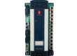
Sam Electronics IOM 402
Key Technical Specifications
- Nominal Voltage: 24 V DC (Marine standard tolerance)
- Digital Inputs: 16 channels (typical configuration)
- Analog Inputs: 8 channels (supporting PT100, 4-20mA, or 0-10V)
- Digital Outputs: 8 relay or transistor outputs
- Communication: Internal System Bus for MCS 2200 / HDC racks
- Mounting: Rack-mount Eurocard format (19-inch subrack compatible)
- Protection: Marine-grade conformal coating against salt mist and humidity
- Certification: DNV-GL, ABS, and Lloyd’s Register compliant
- Resolution: 12-bit ADC for precise analog sensing
Installation & Configuration Guide
Phase 1: Pre-Installation
Estimated time: 15 minutes
⚠️ Marine Safety Protocol:
- Before replacing the IOM 402, switch the Alarm Monitoring System (AMS) or Engine Control System (ECS) to “Local” or “Manual” mode.
- Inform the Bridge and the Duty Engineer that sensors associated with this module will be temporarily offline.
- Check the DIP Switch Settings on the side or rear of the 271.149 244 module. These must match the old module exactly to ensure the correct Node ID.
Preparation:
- ESD-safe wrist strap.
- Flathead screwdriver (for terminal blocks).
- Extracting tool (if the rack is tightly packed).
Phase 2: Removal
Estimated time: 10 minutes
- Terminal Disconnection: If the module uses plug-in terminal strips, pull them firmly but gently. If hard-wired, label every wire (Terminals 1–48) using heat-shrink or clip-on tags.
- Release Screws: Loosen the two captive thumb screws on the front panel of the IOM 402.
- Extraction: Use the module handles to pull the card straight out of the backplane. Avoid touching the gold-plated pins on the rear DIN connector.
Phase 3: Installation
Estimated time: 15 minutes
- Alignment: Align the IOM 402 PCB with the top and bottom guide rails of the subrack.
- Engagement: Slide the module in until the rear connector meets the backplane. Press firmly until the front plate is flush with the rack.
- Securing: Tighten the captive screws to ensure the module is vibration-proof.
- Wiring: Re-attach the terminal blocks.
- Pro-tip: Inspect the terminal pins for “greenish” corrosion (verdigris). If present, clean with an electronic contact cleaner before reconnecting.
Phase 4: Power-On & Testing
Estimated time: 30 minutes
- Power Up: Switch on the 24 V DC control power.
- LED Diagnostics:
- RUN (Green): Should be flashing or steady, indicating the microprocessor is active.
- ERR (Red): Should be OFF. If it stays ON, there is a backplane communication error.
- System Sync: The MCS 2200 system should automatically detect the new module. Check the “I/O Status” page on the workstation.
- Loop Test: Perform a “Function Test” by triggering a digital input (e.g., a bilge high-level switch) and verifying the alarm pops up on the HMI.
Customer Cases & Industry Applications
Case 1: Bilge & Ballast System Restoration
Situation: A container vessel at sea reported a failure in its ballast water control system. Several valves were unresponsive, and the HMI showed “I/O Failure” for Module Rack 4. The faulty unit was identified as a Lyngso Marine IOM 402.
Task: The vessel could not adjust its trim for upcoming port operations. The OEM lead time for this legacy 271.149 series part was “Indefinite” due to discontinuation.
Action: We shipped a New Surplus 271.149 244 module from our emergency stock. The part was delivered via a supply boat during the vessel’s canal transit.
Result: The onboard ETO followed our installation guide and had the system 100% operational within an hour. The vessel avoided port delays and potential safety fines.
Frequently Asked Questions (FAQ)
Q1: What is the difference between version 271.149 244 and other 271.149 variants? A: The suffix (e.g., 244) often denotes a specific I/O mix (number of analog vs digital points) or a specific firmware revision. As a Spare Parts Manager, I recommend matching the suffix exactly. If yours is different, contact me to check cross-compatibility in our technical database.
Q2: Does this module require software programming? A: The IOM 402 is a “slave” device. It doesn’t store the main program, but its DIP switches must be set correctly so the “master” controller knows which signals are connected to it.
Q3: Can I use this in a Sam Electronics HDC system? A: Yes. Sam Electronics and Lyngso Marine were part of the same group, and the IOM 402 / 271.149 hardware is standard across both the HDC and MCS 2200 automation lines.
Q4: Is it safe to buy “New Surplus” for an aging ship? A: It is often the only safe way. “Refurbished” boards from unknown sources may have been exposed to sea air or heat for years. Our New Surplus stock is kept in ESD-shielded bags in a climate-controlled warehouse, preserving the component’s MTBF.
Q5: What if the module doesn’t work after I install it? A: First, check the backplane voltage (must be 24 V). Second, verify the DIP switch settings. If it still fails, we provide a 1-year “Hassle-Free” replacement warranty—we’ll ship another unit immediately to get your ship moving.