
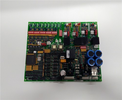
The GE DS200DCFBG1BNC (DS200DCFBG1B) is a specialized Power Supply and Control Board within the General Electric Speedtronic™ Mark V and EX2000 excitation systems. This board is engineered to provide regulated DC power and localized control logic for high-power industrial drives and turbine control architectures. The “DCFB” board is essential for converting source power into the various logic-level voltages required by peripheral boards while monitoring the health of the power distribution network.
Product Specifications
Technical Parameters
- Model Identification: DS200DCFBG1BNC / DS200DCFBG1B
- Manufacturer: General Electric (GE)
- System Series: Mark V Speedtronic / EX2000
- Primary Function: DC Power Distribution and Signal Processing
- Voltage Inputs: 115V AC / 230V AC or 125V DC (System dependent)
- Output Channels: Regulated ±5V, ±15V, and 24V DC for logic and relay control.
- Protection: Integrated fuse protection for individual output branches.
- Rev Code: G1BNC (Signifies specific hardware revision and connector population).
Physical Datasheet
- Dimensions: ~240mm x 175mm (Large format control board)
- Weight: 0.65 kg (1.43 lbs)
- Country of Origin: USA
- Mounting: Vertical or Horizontal rack mounting via standard Mark V standoffs.
- Connectors: Multi-pin ribbon headers and terminal blocks for field/bus integration.
Application Fields
The DS200DCFBG1BNC is predominantly utilized in high-output energy sectors:
- Excitation Systems: Providing core power for the EX2000 excitation control used in large synchronous generators.
- Gas & Steam Turbines: Serving as a power management node within Mark V TMR (Triple Modular Redundant) control racks.
- Heavy Industrial Drives: Used in DC-2000 drive systems for paper mills, steel rolling plants, and mining hoists.
- Renewable Energy: Integrated into legacy wind turbine pitch control systems and large-scale solar inverters.
Product Usage Instructions
- ESD Safety: Before handling the DS200DCFBG1BNC, ensure you are wearing a grounded anti-static wrist strap. The board contains CMOS components highly sensitive to static discharge.
- Jumper Verification: Before installation, compare the jumper settings (JP1, JP2, etc.) of the new board with the one being replaced. Jumpers configure the board for specific input voltages and signal routing.
- Fuse Inspection: Check all onboard fuses prior to installation. A blown fuse on the DCFB board can cause downstream boards to lose power, leading to system-wide “Loss of Communication” faults.
- Wiring: Use the multi-pin ribbon cables to connect the board to the main backplane. Ensure the connectors are fully seated and the locking tabs are engaged.
- Diagnostic Check: Upon power-up, observe the onboard status LEDs. A steady “Power OK” light indicates the voltage regulators are functioning. Use a multimeter to verify the test points (TP) for ±5V and ±15V if logic errors persist.
Q&A – Frequently Asked Questions
Q: What is the difference between the DS200DCFBG1B and the DS200DCFBG1BNC? A: The “NC” suffix often denotes “No Connectors” or a specific variation in the populated terminal blocks. However, in many GE systems, they are functionally identical for core power tasks. Always check your specific rack clearance and cable layout.
Q: Can this board be used in a Mark IV system? A: No. The DS200 series is specifically designed for the Mark V and EX2000 architecture and is not electrically compatible with the older Mark IV hardware.
Q: Where can I check for availability and current pricing? A: For official quotes, expedited international shipping, and availability of new or refurbished units, please visit our GE DS200DCFBG1BNC Resource and Inquiry Center.
Product Related News
In May 2026, the GE DS200DCFBG1BNC remains a critical component for the global energy infrastructure. As many power plants enter “Lifecycle Extension” phases, the demand for high-quality power boards has increased to replace aging units that have faced thermal stress over decades of operation. Industry reports indicate that replacing the DCFB board is often the first step in resolving intermittent “flicker” faults in legacy turbine controllers. To support these efforts, specialized testing labs have introduced enhanced thermal imaging services for refurbished DS200 boards, ensuring that all voltage regulators operate within peak efficiency parameters before deployment back into the field.


