
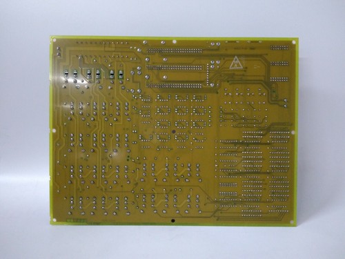
The GE DS200TCTGG1AFF is a specialized terminal board designed for the Mark V Speedtronic™ Turbine Control System. It functions as the primary interface for processing signals related to turbine speed and synchronization. Specifically, the TCTG board is utilized within the <RST> protective cores to handle signals from magnetic speed pickups and to coordinate with the protective voting logic that prevents over-speed conditions. The “AFF” suffix indicates a specific hardware revision and functional grouping that includes specialized EPROMs and component configurations for precise frequency measurement.
Key Product Specifications
- Part Number: DS200TCTGG1AFF
- System Series: Mark V Speedtronic (DS200)
- Module Type: Turbine Control / Speed Terminal Board
- Inputs: Accepts 9 magnetic pickup (MPU) signals (3 per core in
<RST>) - Signal Processing: Converts analog frequency signals from speed sensors into digital data for the controller.
- Protection: Integrated circuitry for emergency over-speed trip logic.
- Connectivity: Features multiple vertical pin connectors for ribbon cable interfacing with the TCQC board.
- Dimensions: 165 mm x 115 mm x 25 mm
- Weight: 0.45 kg
- Country of Origin: USA
Application Fields
The DS200TCTGG1AFF is a critical safety and control component in:
- Heavy-Duty Gas Turbines: Monitoring the rotational speed of the compressor and turbine shafts in GE Frame 6, 7, and 9 units.
- Steam Turbine Control: Providing frequency feedback for speed governing and synchronization to the grid.
- Emergency Trip Systems (ETS): Acting as the front-end interface for the redundant trip voting process.
- Industrial Power Generation: Ensuring stable frequency regulation in island-mode or grid-parallel operations.
Usage Instructions
- Preparation: Power down the Mark V panel and ensure all input signals from the magnetic pickups are isolated. Verify that the turbine is at zero speed before attempting replacement.
- Jumper Verification: Before installation, compare the jumper settings on the new DS200TCTGG1AFF with the board being removed. These jumpers often define the sensitivity thresholds for the speed sensors and must match the field device specifications exactly.
- Mounting: Align the board with the standoffs in the
<R>,<S>, or<T>core of the Mark V cabinet. Secure the board using the original mounting screws to ensure proper grounding and vibration resistance. - Wiring and Connection: Carefully attach the 50-pin ribbon cables to the J-connectors. Ensure the cables are seated correctly and that the locking tabs are engaged. Reconnect the field wiring for the magnetic pickups to the terminal screw blocks.
Q&A – Frequently Asked Questions
Q: Can the DS200TCTGG1AFF be used in a Mark VI system? A: No, the TCTG board is strictly designed for the Mark V Speedtronic architecture. The Mark VI uses different I/O architectures such as the TBCS or TPRO boards for speed sensing.
Q: What happens if one of the three redundant speed signals fails? A: Because the Mark V utilizes Triple Modular Redundant (TMR) logic, the system will identify the failed signal as a “Diagnostic Alarm” but will continue to operate safely using the signals from the remaining two cores.
Q: Is it necessary to recalibrate the speed sensors after replacing this board? A: Usually, no calibration of the physical sensors is required. However, you should verify the speed readings at the HMI once the system is powered to ensure the board is correctly processing the incoming frequency.
Product News: Maintaining Mission-Critical Safety
As the Mark V system ages, the DS200TCTGG1AFF remains a high-priority spare part for power plants worldwide. Its role in over-speed protection makes it an “insurance” component against catastrophic shaft failure. Technical distributors have noted that many facilities are now opting for “AFF” revision boards that feature improved signal filtering components, which help reduce nuisance alarms caused by electrical noise in the turbine enclosure. By keeping certified, tested TCTG boards in stock, plant operators can ensure that their legacy control systems maintain the high Safety Integrity Level (SIL) required for modern power generation standards.


