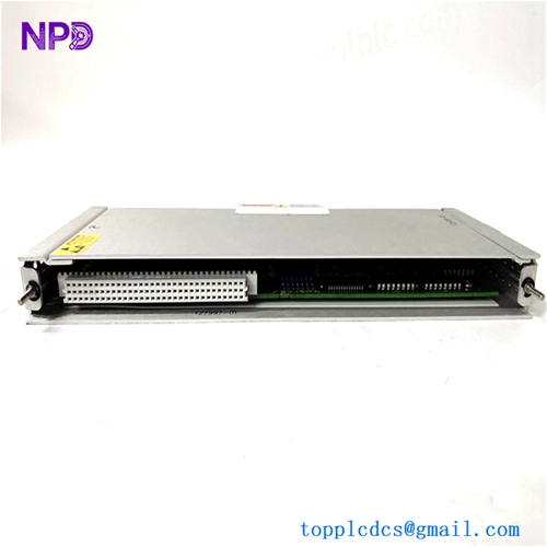
Description
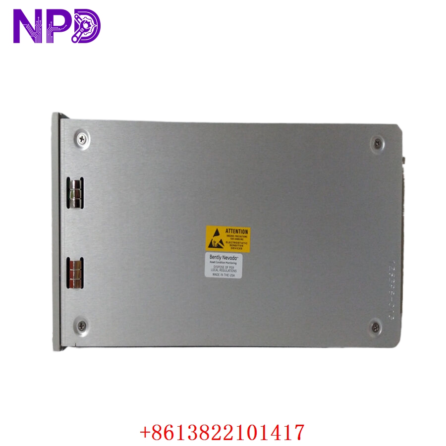
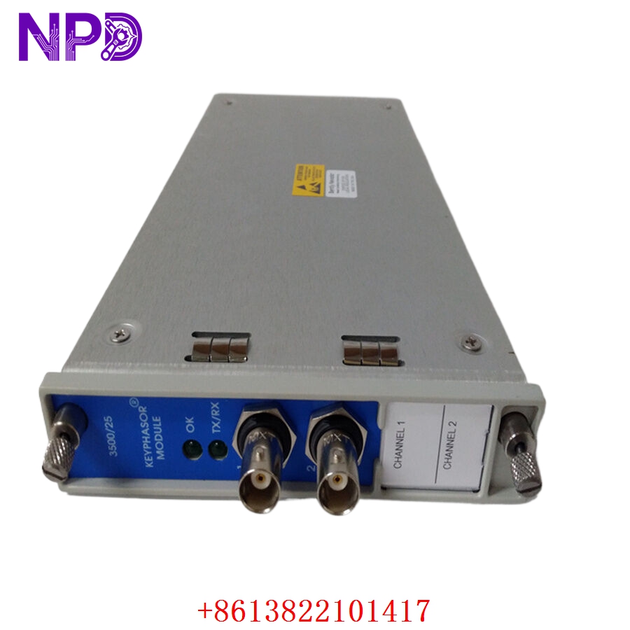
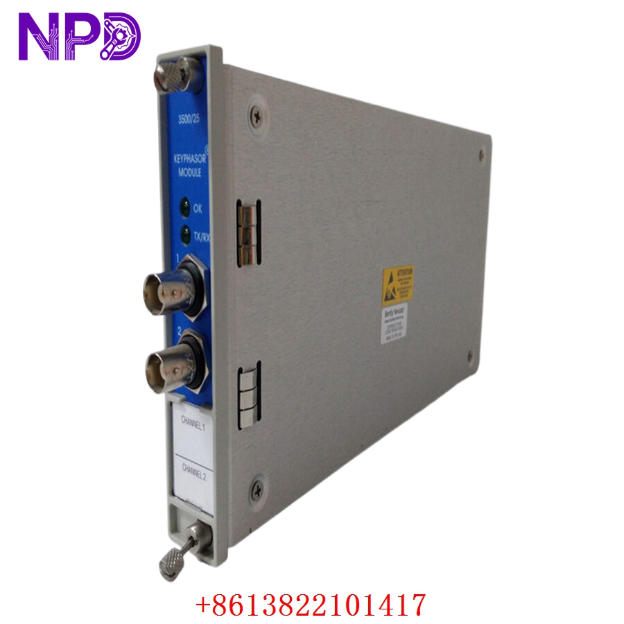
The Bently Nevada 3500/25 Enhanced Keyphasor Module is a half-height, two-channel module utilized within the industry-standard 3500 Machinery Protection System rack. This specialized card processes input signals from proximity probes or magnetic pickups to provide precise digital phase and speed measurements (Keyphasor signals). These tracking metrics allow the 3500 system to calculate accurate rotational speed, vector parameters, and synchronized vibration data. The information is critical for machinery diagnostics, predictive maintenance, and emergency trip protection on high-speed rotating equipment.
To source genuine protection components and maintain maximum uptime across your rotating assets, visit the Bently Nevada Machinery Protection portal.
BENTLY 3500/25
BENTLY 3500/25
BENTLY 3500/25
BENTLY 3500/25
Technical Specifications
- Manufacturer: Bently Nevada (Baker Hughes)
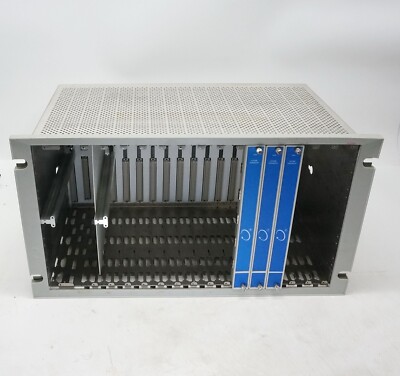
- Series: 3500 Series Machinery Protection System
- Model Keyword: BENTLY NEVADA 3500/25 Keyphasor Card
- Module Type: Enhanced Keyphasor Module (Half-height)
- Dimensions: 12.0 cm x 2.4 cm x 24.1 cm
- Weight: 0.46 kg (1.01 lbs)
- Country of Origin: United States (USA)
- Signal Inputs: Accepts up to 2 single-channel inputs from proximity probes, magnetic pickups, or optical sensors
- Input Impedance: 20 k\Omega standard
- Signal Output range: Isolated outputs corresponding to rotational speed, phase angle, and pulse frequency
- Power Consumption: 3.2 Watts typical
Application Fields
The 3500/25 module is an essential asset for vibration analysis and machinery safety inside complex, heavy-duty industrial environments:
- Power Generation Plants: Phase monitoring and speed tracking on steam turbines, gas turbines, and massive generator rotors.
- Petrochemical Facilities: Continuous protection for high-speed centrifugal compressors, turboexpanders, and process pumps.
- Steel and Mining Mills: Structural health monitoring for large industrial blowers, ventilation fans, and motor-driven gearboxes.
- Maritime Propulsion: Monitoring main shaft dynamics and rotational speed sync for massive shipping vessels.
Product Installation and Usage Instructions
- Chassis Preparation: De-energize the specific section of the 3500 rack frame if local site safety protocols require it. Wear an anti-static ESD wrist strap securely connected to a verified ground point before opening the hardware package.
- Positioning the Module: The 3500/25 is a half-height card and must be installed into a designated half-height slot location. If utilizing a full-height slot, ensure the proper half-height chassis execution panel or guide sleeve is properly installed.
- Module Insertion: Align the card along the guide rails and push firmly inward until the backplane multi-pin interface pins are entirely mated with the main rack connector block.
- Hardware Fastening: Secure the hardware by hand-tightening the dual captive screws located on the module faceplate to avoid vibration-induced loose connections.
- Software Calibration: Fire up the 3500 Rack Configuration Software via your engineering workstation. Define input sensor parameters (e.g., threshold voltage, hysteresis, pulses per revolution) and verify the active Keyphasor diagnostic pulses through the system log.
Frequently Asked Questions (Q&A)
Q: What is the main upgrade advantage of the “Enhanced” Keyphasor over older legacy versions?
A: The Enhanced 3500/25 variant provides superior processing capabilities, allows for multi-event pulses per revolution, and provides advanced internal self-tests to identify line breaks or sensor anomalies much faster.
Q: Can a single 3500/25 module supply Keyphasor signals to multiple cards within the same 3500 rack?
A: Yes. The 3500 system architecture allows Keyphasor signals processed by the 3500/25 card to be distributed across the internal rack backplane to other monitoring cards (like 3500/42M or 3500/40M) that require phase-synchronized calculations.
Q: Does the 3500/25 package include the rear I/O module?
A: No. The standard model configuration numbers typically represent the internal main control card. The rear I/O module (such as part number 125792-01 for standard I/O or 149369-01 for internal termination) must be paired and ordered based on your field wiring architecture.
Q: What do the front panel indicator lights signify on this board?
A: The front panel includes an “OK” LED (green indicates normal internal module operation) and a “TX/RX” LED (flashing amber implies active communication across the rack backplane).
Recommended Hot Stock Models
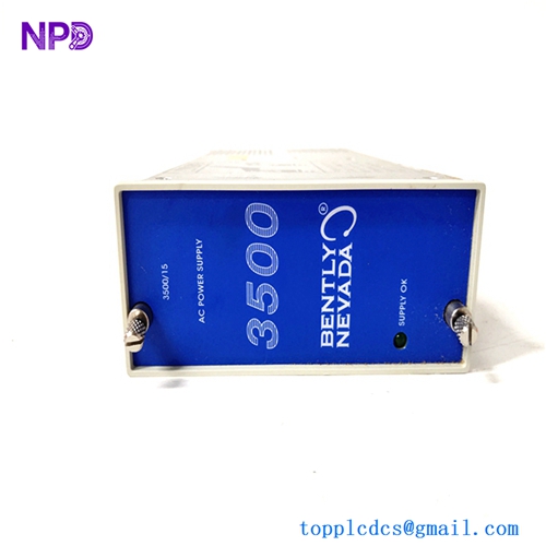
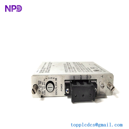
- BENTLY NEVADA 3500/15 127610-01
- BENTLY NEVADA 3500/20 125744-02
- BENTLY NEVADA 3500/42M 176449-02
- BENTLY NEVADA 3500/32 149986-02
- BENTLY NEVADA 3500/50 133388-01
- BENTLY NEVADA 3500/92 136180-01
- BENTLY NEVADA 3500/40M 140734-01
- BENTLY NEVADA 3500/22M 146031-01