
Description
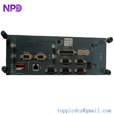
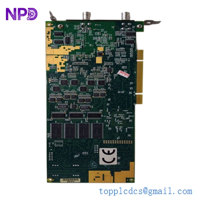
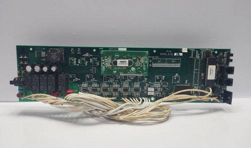
The 5945.576.13 (often identified by the board marking 30D393) is a precision-engineered Electronic Controller Board. This component is designed to manage specific logical sequences and signal processing for industrial automation systems, including specialized refrigeration units, HVAC control systems, or complex machinery controllers. As a central processing element, it interprets sensor data and executes commands to ensure the operational stability and performance of the host equipment.
📋 Technical Specifications
- Model Number: 5945.576.13
- Board Marking: 30D393
- Function: Integrated Logic and Control Processing
- Input/Output: Multi-channel analog and digital I/O
- Mounting Type: Enclosure/Rack Mount
- Dimensions: 8.5 x 6.0 x 1.5 inches (Approx.)
- Weight: 0.9 lbs (0.41 kg)
- Country of Origin: Industrial EU/International Standard
⚙️ Application Areas
- Industrial Climate Control and Refrigeration
- Automated Manufacturing Logic Gates
- Process Control Loops
- Building Management Systems (BMS)
- Legacy Machinery Automation Upgrades
🛠️ Operating Instructions & Guidelines
- Installation: Ensure the board is installed in an ESD-safe (Electrostatic Discharge) environment. Secure the board using the provided mounting standoffs and ensure the connector pins are fully aligned before pressing down to seat the card.
- Environmental Requirements: Operate within a temperature range of 0°C to 50°C. Maintain low humidity levels to prevent condensation or corrosion on the sensitive electronic pathways and solder joints.
- Maintenance: Regularly remove dust buildup using low-pressure dry air. Check for any discoloration of components, which may indicate overheating or an aging capacitor.
⚡ Power Sequence & Operation
- Power-On Sequence: 1. Ensure all field wiring is properly terminated according to the pinout diagram. 2. Verify input voltage levels with a multimeter to ensure they match the required rating. 3. Power up the master control cabinet. 4. Observe the PCB status LEDs for a successful “Power On” or “System Ready” light.
- Power-Off Sequence: 1. Terminate all running automation cycles via the HMI/Software. 2. Turn off the main circuit breaker. 3. Wait for the onboard capacitors to discharge completely (typically 60 seconds) before handling the board.
- Step-by-Step Operation: 1. Initialize the communication link with the main controller. 2. Verify that the sensor inputs are displaying correct real-time values. 3. Test output triggers to ensure relays or valves operate correctly. 4. Monitor the system for continuous stability under load.
❓ Frequently Asked Questions (Q&A)
- How do I handle this board safely? Always wear an anti-static wrist strap connected to a proper ground point. Never touch the electronic components or pins directly, as oils from skin or static discharge can cause permanent damage.
- What does the board marking “30D393” indicate? This is usually a manufacturing code for the specific PCB revision. When ordering replacements, ensure this marking matches your current board to guarantee firmware and pin-compatibility.
- Can I repair a damaged trace on the board? Board-level repair requires specialized skills and tools. In industrial applications, it is highly recommended to replace the entire board with a factory-tested unit to avoid unexpected failures during production.
- What is the most common cause of board failure? The most common causes are power surges, exposure to high humidity (corrosion), and vibration-induced stress on soldered components.