
Description
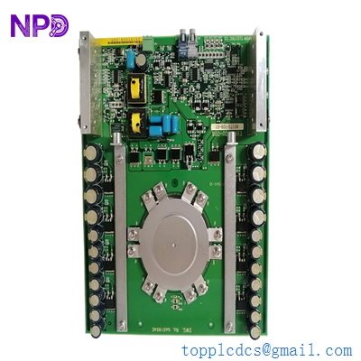
- Model: 81001-450-53-R
- Brand: Mitsubishi Electric (Japan)
- Series: Melpro / Power System Protection
- Core Function: Specialized protection relay and monitoring unit for industrial power distribution systems.
- Product Type: Digital Protection Relay / Power Management Module
- Key Specs: 450V Class, High-speed tripping, integrated status display
- Voltage Rating: Suitable for 450V class AC systems
- Protection Functions: Typically includes Overcurrent (OC), Undervoltage (UV), and Overvoltage (OV) logic (Check specific configuration code)
- Measurement: Real-time monitoring of current and voltage parameters
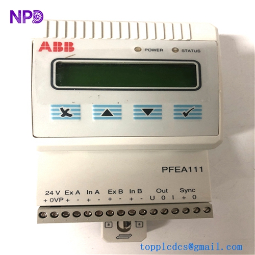
- Display: Integrated LED/LCD segment display for fault codes and monitoring data
- Communication: Supports Mitsubishi’s proprietary bus or serial links for SCADA integration
- Output Contacts: Heavy-duty trip contacts and signaling relays
- Mounting: Rack-mount or flush-mount within protection panels
- Power Supply: Internal DC-to-DC converter (Check label for 24-110V DC input requirements)
MITSUBISHI 81001-450-53-R
Installation & Configuration Guide
Phase 1: Pre-Installation (Estimated time: 20 minutes) ⚠️ Safety First:
- This module is part of a High-Voltage Protection circuit. Ensure the CT (Current Transformer) and PT (Potential Transformer) circuits are isolated and shorted/grounded where necessary.
- Settings Audit: Before removing an old relay, record the trip set-points (Current thresholds, time delays, and curves).
- Verify the “-R” suffix. In Mitsubishi nomenclature, this often denotes a specific revision or a “Refined” hardware version.
Phase 2: Removal (Estimated time: 10 minutes)
- Short the CTs: If the relay is connected to live Current Transformers, you MUST short-circuit the CT secondary terminals before disconnecting. An open CT secondary can generate lethal voltages.
- Disconnect Terminals: Remove the wiring from the rear screw terminals. Label each wire according to the Mitsubishi terminal number (e.g., A1, A2, B1…).
- Unmount: Remove the panel mounting screws and slide the unit out.
Phase 3: Installation (Estimated time: 15 minutes)
- Physical Mount: Insert the new 81001-450-53-R into the panel cutout. Secure the mounting brackets.
- Wiring: Reconnect the CT, PT, and power supply wires. Ensure all terminal screws are tightened to the specified torque to prevent arcing.
- Grounding: Ensure the frame ground terminal is connected to the cabinet’s grounding bar.
Phase 4: Commissioning & Testing (Estimated time: 45 minutes)
- Apply control power. The relay should perform a self-test and display “Normal” or a station ID.
- Parameter Entry: Use the front panel buttons to enter the trip settings you recorded in Phase 1.
- Injection Test: Use a secondary injection test set to simulate an overcurrent or overvoltage event. Verify that the relay trips within the specified time curve.
- Target Reset: Clear any fault flags and ensure the “Trip” contact successfully signals the circuit breaker.
MITSUBISHI 81001-450-53-R
Customer Cases & Industry Applications
Case 1: Marine Switchboard Protection A cargo vessel in the Pacific experienced a failure in its main generator protection relay. The Mitsubishi 81001-450-53-R was no longer available from the local distributor. We delivered a New Surplus unit to the vessel’s next port of call in 4 days. The chief engineer replaced the unit during a brief engine shutdown, restoring the safety of the ship’s 450V distribution system and allowing the vessel to clear its insurance survey.
Case 2: Industrial Manufacturing Plant Stability A steel mill in Japan utilized Melpro relays to protect their critical rolling mill motors. An aging relay began “nuisance tripping,” causing thousands of dollars in production loss. By replacing the unit with our New Surplus 81001-450-53-R, the mill eliminated the false trips while maintaining the high-speed protection required to prevent motor burnout.
Frequently Asked Questions (FAQ)
Q: Can I use this relay for a 660V system? A: No. The “450” in the part number indicates it is designed for 450V class systems. To be honest, using it on a higher voltage system will likely lead to insulation failure and catastrophic damage to the relay.
Q: What is the purpose of the “-R” at the end of the part number? A: Usually, Mitsubishi uses “-R” to indicate a revision or a specific relay type (like “Rear-connected” or “Ruggedized”). Always check the side label of your original unit to ensure the input/output ratings match.
Q: Why is my relay showing an “ERR” code on startup? A: Check the internal battery or the watchdog timer. If it’s a new unit, it may indicate a configuration mismatch or that the sensing inputs (PT/CT) are not yet detected.
Q: Is “New Surplus” reliable for electrical protection? A: Absolutely. Mitsubishi protection relays are built to last decades. “New Surplus” units have zero hours of operation, meaning the internal capacitors and trip relays have not been subjected to the electrical heat and stress of an active switchgear. We provide a 1-year warranty for your peace of mind.
Q: Do I need special software to program it? A: Most Melpro units can be fully configured using the front panel buttons and display. However, some advanced models support a PC connection for downloading fault records. Check the front port for a communication jack.
I’m always open to corrections if I get something wrong; the best way to handle that is to just tell me what I missed or what I need to know! You can also always turn off the use of this personal context in your settings.