
Description
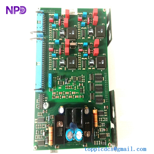
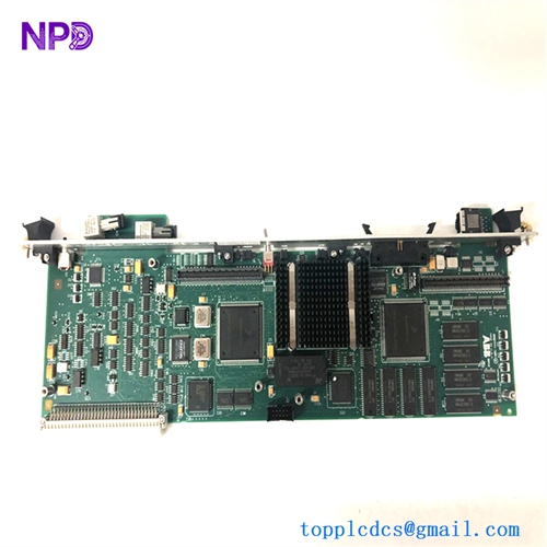
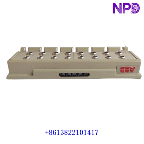
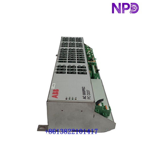
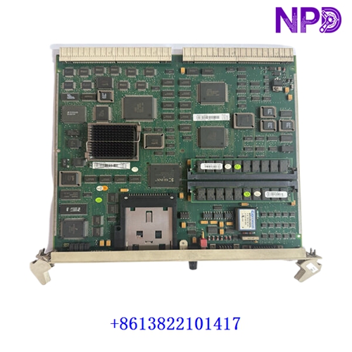
The ABB 086407-502 is a specialized industrial control and processing module—frequently deployed as a stepper/linear control or intelligent I/O related card within high-reliability automation environments. It is engineered to provide precise motion or signal coordination, rapid data processing, and stable integration across complex industrial systems, power generation setups, and heavy manufacturing lines.
www.chnscs.com
- Brand: ABB
- Model: 086407-502
- Series: Industrial Automation / Control Hardware
- Product Name: Control / Motor Interface Board
www.chnscs.com
- Place of Production: Sweden / Germany
- Lifecycle Status: Industrial Core / Spares Line
- Dimensions: Standard Modular Form Factor
- Weight: Approx. 1.2 – 3.2 kg (depending on configuration variant)
xiongba
- Original Origin: European Union
- Power Consumption: 24V DC / Max 15W
📋 Initial Startup Inspection Checklist
- 🔍 Visual Integrity: Inspect the printed circuit board, edge connectors, and surface components for any shipping damage, bent pins, or moisture exposure.
- 🔍 Firmware & Revision Match: Confirm that the board hardware revision aligns completely with the system engineering configuration and software requirements.
- 🔍 Supply Voltage Verification: Measure the input power rails using a calibrated multimeter to guarantee stable delivery within the designated operational envelope.
- 🔍 Grounding Continuity: Verify that all shielding connections and backplane ground paths are tightly secured to minimize electromagnetic interference (EMI).
- 🔍 Environmental Assessment: Check that ambient cabinet temperatures and relative humidity remain well within specified operating thresholds.
🛠️ Routine Maintenance and Servicing
Regular maintenance prevents drift in operational performance and extends the lifespan of sensitive electronic components.
- 🔧 Dust Removal: Carefully clear accumulated dust from the board surface and card slots using clean, dry, oil-free low-pressure compressed air.
- 🔧 Connector Maintenance: Annually inspect plug-in terminal blocks and edge contacts to ensure no oxidation or loosening has occurred due to mechanical vibration.
- 🔧 Diagnostic Verification: Routinely monitor board status LEDs and system error logs via the engineering workstation to detect early operational anomalies.
- 🔧 Parameter Backup: Maintain secure, up-to-date archives of configuration files for rapid recovery in the event of replacement.
🔍 Troubleshooting and Common Faults
Systematic fault diagnosis minimizes downtime and isolates errors efficiently.
- ⚠️ Fault Symptom 1 (No Power / Status LED Unlit): Check input power feeds, local board fuses, and slot insertion depth. Replace blown fuses strictly with matching factory ratings.
- ⚠️ Fault Symptom 2 (Communication or Signal Failure): Inspect interface lines, communication cables, or connector pins for physical damage, loose contact, or bad termination.
- ⚠️ Fault Symptom 3 (Processing Errors / Fault Trips): Verify input signal ranges, check for ground loops, and perform a system reset or diagnostic check through the host controller software.
⚡ Safety Precautions
- 🛡️ Qualified Personnel Only: Installation, calibration, and troubleshooting must be executed exclusively by certified instrumentation and electrical engineers.
- 🛡️ Electrostatic Discharge (ESD) Control: Always wear an approved grounded wrist strap and handle the circuit board strictly by its edges or non-conductive mechanical framework.
- 🛡️ Energy Isolation: Completely de-energize the rack and lock out associated power sources prior to inserting or extracting the module.
❓ Frequently Asked Questions (Q&A)
- 💡 Q1: Can this control module be hot-swapped while the enclosure is live?
- A1: Live extraction or hot-swapping is generally not permitted unless explicitly supported by your specific system rack architecture. Power down the system to prevent electrical spikes.
- 💡 Q2: What should be done if the module encounters an unresponsiveness fault upon startup?
- A2: Disconnect power, verify that the board is seated firmly in its designated backplane slot, check input power stability, and review the main controller error log.