Description
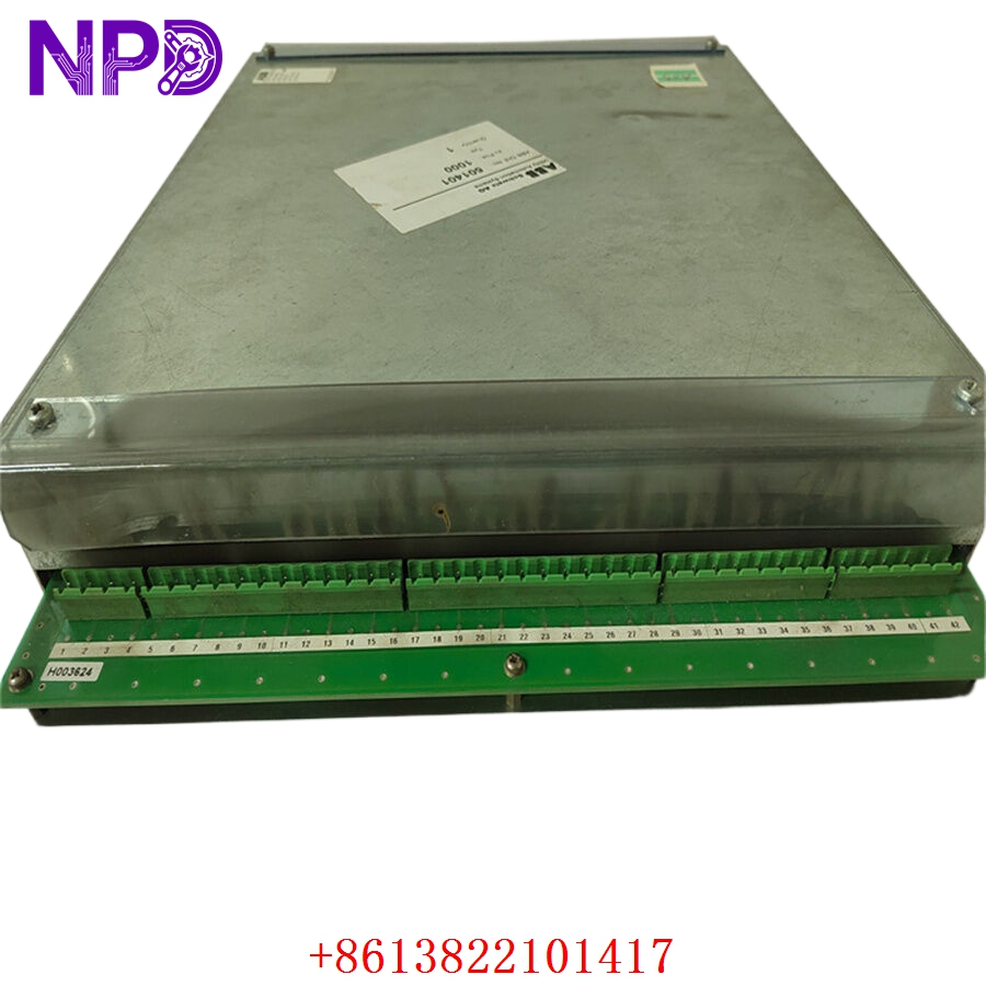
- Model: ABB 216GD61a (Global ID: HESG324436R3-A / Base Card No: HESG324428)
- Brand: ABB (Switzerland)
- Series: 216 Series Monitoring & Protection System (Commonly integrated with high-voltage circuit breaker control networks and excitation systems)
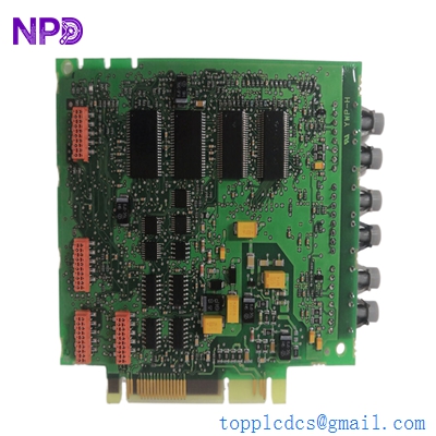
- Core Function: Monitors auxiliary contacts, coil currents, and diagnostic timing metrics of high-voltage circuit breakers, Brand New Surplus condition
- Type: Circuit Breaker Diagnostic / Supervision Input Card
- Key Specs: Multichannel optocoupler isolation | Real-time current wave logging | System backplane bus communications
- Operating Auxiliary Power: Supplied via 216 series rack backplane (typically +5 V DC / \pm15 V DC rails)
- Binary Input Channels: Multi-point high-isolation digital inputs designed for breaker status contacts
- Coil Supervision Inputs: Dedicated input channels for measuring circuit breaker trip and close coil current profiles
- Isolation Barrier: Onboard optocouplers providing up to 2,500 V AC RMS galvanic isolation
- Sampling Rate: High-speed internal signal conversion for millisecond-accurate event timing recording
- Status Signaling: Front-panel array of diagnostic diagnostic LEDs (Run, Fault, Channel Input Active)
- Backplane Bus Interface: Parallel data bus architecture matching ABB 216 rack systems
- Climatic Compliance: Operating range from -10 °C to +55 °C (for indoor sub-station or cabinet deployment)
Part 4: Installation & Configuration Guide
Phase 1: Pre-Installation (Estimated Time: 20 minutes)
⚠️ Safety First:
- Coordinate with your station operations manager to place the corresponding high-voltage breaker node into local maintenance isolation. Never pull a diagnostic card while the breaker safety trip loops are active and armed.
- Trip the auxiliary control power distribution breakers feeding the target 216 series rack chassis.
- Apply standard Lockout/Tagout (LOTO) padlocks and warning tags to the rack’s primary power switches.
- Wait 5 minutes for the rack power supply filter circuits to discharge completely before touching any components.
Tool Preparation:
- Static-dissipative grounding wrist strap and an ESD-safe workspace mat
- Flathead instrument screwdriver (2.5 mm precision blade)
- Phillips screwdriver for securing rack panel screws
- Fluke 115 Digital Multimeter
- Wiring labels, marking pen, and a high-resolution camera
Backup Procedures:
- If the rack system connects to an engineering station, upload and save the current parameters, system log events, and hardware mapping profile for the target rack slot before pulling any hardware.
- Take clear, well-lit photos of the front faceplate configuration and any field wires connected to the terminal blocks of the card.
Phase 2: Removal (Estimated Time: 10 minutes)
Steps:
- Verify with your multimeter that the field wiring terminal strips connected to the 216GD61a front faceplate read 0 V DC/AC.
- Carefully loosen the terminal block wire screws and slide the individual field wires out. Wrap temporary electrical tape over any bare wire tips.
- Locate the top and bottom panel mounting screws on the card’s front plate.
- Back out the screws using your Phillips screwdriver (these are often captive style and will remain attached to the faceplate).
- Grasp the module handle firmly and pull straight out. This unseats the board from the parallel backplane socket connector pins.
- Guide the card out of its slot rails and slide it directly into an ESD shielding bag.
⚠️ Key Notes:
- Inspect the old board for any physical revisions, specialized jumper wires, or field-installed component changes that might need to be replicated on your replacement module.
Phase 3: Installation (Estimated Time: 15 minutes)
Steps:
- ESD Protection: Fasten your grounding wrist strap to a verified ground point before opening the sealed antistatic packaging containing the new surplus HESG324436R3-A card.
- Jumper and Dip Switch Replication: Look closely at the raw base board circuit layer (marked HESG324428). You must check all physical jumpers or DIP switches and set them to match your decommissioned card exactly. These switches determine slot addressing, signal logic, or input voltage scaling.
- Insert Card: Align the upper and lower edges of the circuit board within the designated card guide tracking lanes of the 216 rack slot.
- Seat Connectors: Slide the card smoothly inward until it contacts the backplane. Press firmly until the rear connector seats completely into the backplane pin assembly.
- Secure Panel: Tighten the top and bottom faceplate screws to lock the card to the rack frame.
- Reconnect Terminals: Land the field wiring pairs back onto the terminal blocks using your reference labels and photos, making sure all terminal screws are tight.
Self-Check Checklist:
- [ ] Internal jumper arrays and DIP address maps match the original card exactly
- [ ] Field inputs are re-terminated to their correct channel positions with proper polarity
- [ ] Faceplate mounting screws are screwed down flush with the rack rails
- [ ] No loose wires or stray copper strands are bridging adjacent terminal terminals
Phase 4: Power-On & Diagnostic Testing (Estimated Time: 20 minutes)
Pre-Power Checks:
- Check for any low-resistance shorts to ground across the input lines using your multimeter. Verify that the auxiliary rack voltages match standard factory specifications.
Power-On Steps:
- Clear your tools from the cabinet space and close the auxiliary 216 rack power distribution breaker.
- Monitor Initial LED Status: The front panel RUN (Green) light should illuminate after a brief self-test window. If the FAULT (Red) LED stays lit, turn off power immediately to inspect slot configuration.
- Signal Verification: Cycle the monitored high-voltage breaker locally (if safe to execute during a maintenance window) or simulate an auxiliary contact status signal change. Verify that the corresponding channel LED on the 216GD61a faceplate cycles on and off to match the input.
- Review the central substation control room event logger or diagnostic station interface. Confirm that the module functions normally on the communication network and that no slot mismatch flags are active.
- Clear out any temporary LOTO tags once the diagnostic data stabilizes for 15 minutes. Record the new serial number in the plant asset database.
Part 5: Customer Cases & Industry Applications
Case 1: Restoring Diagnostics for a Key Power Station Substation Breaker
Situation:
A major hydropower generation facility uses an ABB 216 rack control array to manage sub-station equipment and log high-voltage circuit breaker metrics. During a seasonal maintenance cycle, a faulty auxiliary contact circuit sent an unexpected voltage spike into the diagnostic rack, frying the isolation circuits on the main 216GD61a module and knocking out breaker supervision visibility.
Task:
The control room lost real-time tracking of the breaker’s operation timing, which is a critical safety parameter used to detect mechanical sticking or slow clearing speeds. Running the sub-station blind without this diagnostic data violated operating safety guidelines, and the plant faced a forced capacity reduction if a replacement card could not be found quickly.
Action:
The plant’s instrument division reached out to our depot to source an immediate replacement. We pulled an original new surplus 216GD61a HESG324436R3-A module from our climate-controlled warehouse stock. We checked the board traces, verified the galvanic isolation limits of its optocouplers on our test bed, and shipped the part via priority overnight air courier.
Result:
- Uptime Restored: The replacement module reached the generation site within 18 hours of the initial fault. The crew duplicated the address jumpers and finished wiring the terminal connections before noon.
- Safety Verified: The card passed its startup self-test immediately on boot, restoring full circuit breaker diagnostic tracking and allowing the facility to maintain normal grid capacity.
- Customer Voice: “Finding an un-used, factory-clean card for this legacy 216 setup seemed like a long shot. Sourcing it from your inventory saved us from an extended outage window and resolved our safety compliance issue.”
Case 2: Strategic Spares Allocation for an Industrial Grid Interface
Situation:
A heavy manufacturing facility running an intensive electrochemical process relies on an older ABB 216 architecture to manage its main electrical substation. The protection cabinet relies on multiple legacy 216GD61a cards to monitor and log current profiles for the plant’s main supply breakers.
Task:
Knowing that ABB had moved this hardware generation into obsolete status, the plant’s reliability team wanted to secure critical spare parts before the global market supply dried up completely. Using refurbished or repaired pull-outs on critical breaker protection circuits was rejected due to safety concerns.
Action:
The procurement manager contacted us to locate authentic, un-used surplus components. We supplied a matching HESG324436R3-A module inside its original, sealed anti-static factory packaging, complete with clean manufacturing numbers, allowing the facility to confirm the pristine condition of the board before adding it to their safety stock.
Result:
- Long-Term Protection: This strategic purchase provided the plant with a reliable, plug-and-play backup component, ensuring they can keep their legacy control systems running smoothly for years to come without requiring an expensive and un-planned full-system panel upgrade.
Part 6: Frequently Asked Questions (FAQ)
Q1: How do the part numbers 216GD61a, HESG324436R3-A, and HESG324428 work together?
A: These numbers identify the same physical module across different documentation systems at ABB:
- 216GD61a is the structural type and catalog code designation used in engineering manuals to identify this specific circuit breaker diagnostic card.
- HESG324436R3-A is the official global commercial ordering number used to track this specific assembly version and component layout revision level.
- HESG324428 is the base manufacturing number stamped onto the bare green circuit board layer itself before components are populated.
If your old module label shows these numbers, this New Surplus component will drop in as an exact match.
Q2: Why is it critical to match the internal jumpers and DIP switches to our original board layout?
A: The 216GD61a is a versatile interface card designed to sit in various slots along the parallel communication bus of the 216 series rack.
The onboard DIP switches and hardware jumpers govern vital configurations, including its unique communication address on the rack backplane, signal filtering times, and logic states for different contact inputs. Installing a replacement card without matching these settings can prevent the master rack processor from finding the board or lead to false breaker status alarms in the control room.
Q3: What is the purpose of the galvanic isolation optocouplers on this board?
A: High-voltage circuit breaker environments are prone to intense electromagnetic interference (EMI) and transient voltage surges during switching operations.
The onboard optocouplers create a 2,500 V AC galvanic isolation barrier that translates high-voltage field signals into low-voltage light pulses. This design isolates external electrical noise and safely prevents field spikes from travelling along the backplane and damaging the delicate digital processing chips in the rest of the 216 control rack.
Q4: Why buy a New Surplus ABB module instead of a cheaper refurbished option online?
A: Refurbished 216 series cards are typically salvaged from old, decommissioned industrial plants. Third-party repair shops often just clean the outer terminals or replace blown input fuses, leaving the old internal optocouplers and diodes in place. These old components are prone to failing unexpectedly when subjected to continuous thermal variations inside a live substation cabinet.
Our New Surplus units are authentic, un-used modules stored in climate-controlled warehouses. They provide factory-original component lifespans and come backed by a full 12-month warranty, ensuring reliable protection for your machinery without the risks of refurbished hardware.
Q5: How do you verify the signal accuracy of this card before shipping?
A: Every 216GD61a module goes through a rigorous quality check on our specialized testing benches before leaving our facility. We slide the card into a live 216 series rack chassis, apply test voltages across the input channels, and monitor the backplane data bus to ensure every binary input and current wave log updates accurately and cleanly.