
Description
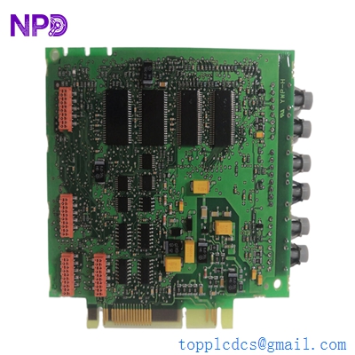
This technical datasheet provides comprehensive specifications, installation procedures, routine maintenance guidelines, troubleshooting steps, safety precautions, and frequently asked questions for the ABB 3BHB003230R0101 drive board incorporating the 5SXE 05-0152 component. Engineered for high-power industrial frequency converters and medium-voltage drives, this high-performance electronic board ensures precise gate control, fast signal processing, and reliable power electronics management.
⚙ Product Technical Parameters
- 1. Brand: ABB
- 2. Model / Part Number: 3BHB003230R0101 / 5SXE 05-0152
- 3. Series: ACS / Industrial Medium-Voltage Drive Control Series
- 4. Product Name: Drive Control / Gate Driver Printed Circuit Board
- 5. Country of Origin: Switzerland / Sweden
- 6. Physical State: Advanced multi-layer surface-mount printed circuit board assembly
- 7. Dimensions: Standard modular drive rack insert format
- 8. Weight: Approx. 0.85 kg
- 9. Origin Location: European Manufacturing Facility
- 10. Power Consumption: Low-power internal control draw governed by the drive converter rail supplies
📋 Initial Operation Checklist
Before installing and energizing the drive board for the first time, verify all physical and electrical configurations to prevent hardware failure or system faults:
- Inspect the PCB traces, components, optical links, and edge connectors carefully for any signs of transit damage or dust contamination.
- Confirm that the main drive power supply is completely de-energized, locked out, and that internal DC link capacitors are fully discharged.
- Verify that all plug-in fiber-optic cables, multi-pin connectors, and mounting hardware are properly aligned and securely seated.
- Ensure ambient operating temperature within the converter cabinet remains strictly between -10°C and +55°C.
- Check jumper configurations and hardware revision compatibility against your specific drive architecture prior to startup.
🛠 Routine Maintenance and Upkeep
Regular maintenance ensures optimal operational longevity and sustained reliability across high-power industrial drive architectures:
- Perform bi-annual visual inspections to check for dust accumulation, environmental moisture, or corrosion on component pins.
- Clean board surfaces gently using a clean, dry, anti-static brush or compressed air; strictly avoid chemical solvents, sprays, or liquids.
- Monitor system diagnostic logs and error counters periodically during scheduled plant maintenance intervals.
- Check chassis mounting screws and terminal connectors annually to prevent loose connections caused by thermal expansion or vibration.
🔧 Troubleshooting and Common Issues
Systematic problem isolation minimizes downtime when operational anomalies or communication faults occur:
- Board Initialization / Fault LED Active: Check internal DC supply voltage rails, verify connector seating, and inspect status indicator lights.
- Fiber-Optic Link Failure: Inspect optical patch leads for damage, check transceiver cleanliness, and verify signal transmission strength.
- Gate Driver Trigger Fault: Verify control signal integrity, check feedback loops, and ensure proper grounding of the drive enclosure.
- Intermittent System Resets: Check for electromagnetic interference (EMI) sources near signal routing and confirm proper cabinet shielding.
🛡 Safety Precautions
Strict adherence to safety guidelines protects personnel from severe electrical hazards and prevents permanent hardware damage:
- Always disconnect and lock out main high-voltage AC and DC power sources before servicing or replacing drive electronics.
- Observe standard electrostatic discharge (ESD) wrist strap handling protocols when interacting with sensitive printed circuit boards.
- Ensure all DC link capacitors are fully discharged down to safe voltage levels before touching internal power components.
- Ensure all wiring and grounding comply strictly with local electrical codes, industrial safety standards, and manufacturer recommendations.
❓ Frequently Asked Questions (Q&A)
- Q1: Does this replacement drive board require configuration or software setup after installation?
- A1: Yes, specific parameter matching, calibration data, and software configuration settings must be verified via the control panel or engineering software tool to match exact application requirements.
- Q2: Can this board be replaced while the drive system is active?
- A2: No, replacing internal drive electronic boards requires a complete system shutdown, power isolation, and capacitor discharge to prevent severe electrical shock and component destruction.
- Q3: What should I do if a fault code persists after installing the new board?
- A3: Verify that all internal connectors and fiber-optic cables are securely locked in place. Check the event logger via the control software to isolate whether the fault originates from the board or external peripheral stages.