Description
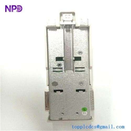
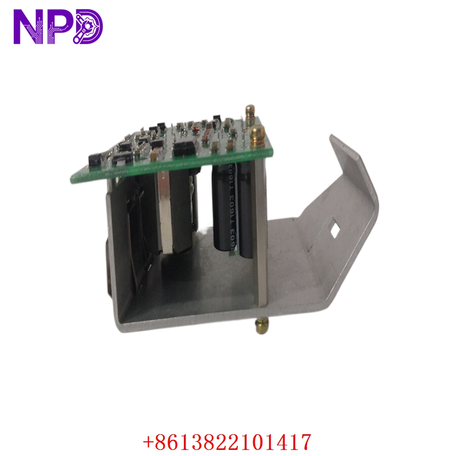
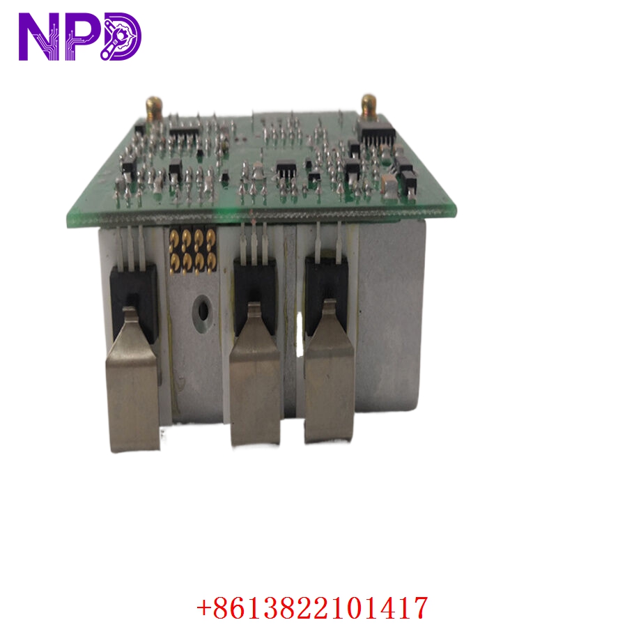
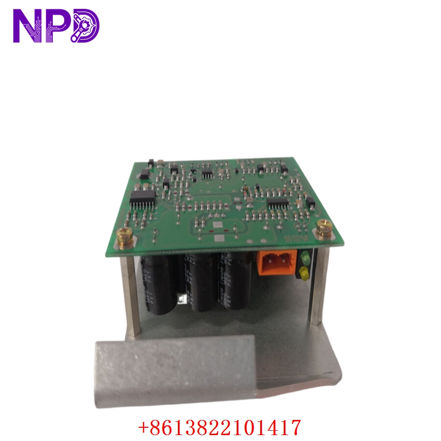
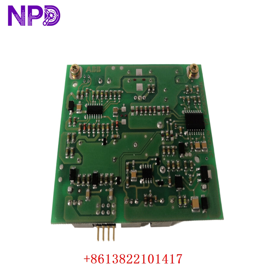
- Model: ABB 3BHB003688R0101 (KUC711AE101 / GUSP Subboard)
- Brand: ABB (Switzerland-Sweden)
- Series: ACS1000 Medium Voltage Drive Series
- Core Function: High-voltage interface board managing real-time signal processing and drive system isolation
- Product Type: Drive Interface Board / PC Board Assembly
- Key Specs: 520 VDC Port Isolation | Multi-Channel High-Speed Signal Handling | Integrated Drive Over-Current Protection
- Input Voltage: 24 V DC internal operating voltage
- Board Topology: Medium voltage drive subboard interface assembly
- Port Isolation Rating: 520 VDC galvanic isolation between control logic and power stage
- Compatible Drive Frameworks: ACS1000 series medium voltage AC drives, select ACS6000 topologies
- Hardware Sub-Classification: GUSP Subboard assembly
- Board Dimensions: 23 cm x 11 cm x 3.4 cm
- Net Weight: 0.35 kg
- Serial Interface Management: Multi-channel integrated high-speed drive communication link
- Onboard Indicators: Multi-status diagnostic LEDs for power rail, signal state, and fault conditions
- Environmental Conformity: G3 conformal coating for harsh industrial atmospheres
Application Scenarios & Engineering Pitfalls
The On-Site Reality
In large-scale process industries utilizing medium voltage drives—like an aeration blower line in a wastewater treatment facility or a main furnace draft fan—the drive isn’t just another component; it’s the heart of the mechanical process. When a high-voltage interface board like the 3BHB003688R0101 breaks down due to a power line surge or localized thermal stress, your process stops dead. Tracking down a factory-new replacement for legacy ACS1000 infrastructure from standard vendor catalogs can leave you dealing with 8-week Lead times, putting millions of dollars of operational throughput at risk.
Typical Deployment Scenarios
- Heavy Metallurgy – Main Extraction and Blast Furnace Fans
Used within ACS1000 drive line-ups to manage high-speed switching feedback, providing high-noise immunity and signal integrity under severe electromagnetic fields.
- Oil & Gas – High-Pressure Pipeline Compressors
Acts as the critical isolation layer between the low-voltage control brain and the high-power medium voltage bridge, preventing control side destruction during high-current faults.
- Power Generation – Boiler Feed Water Pump Inverters
Ensures continuous, deterministic feedback loops back to the primary plant DCS, keeping pump speed tightly matched to continuous steam demand profile.
- Municipal Water Management – Large Lift Station Submersible Drives
Protects control infrastructure from environmental moisture and high thermal swings while reporting sub-millisecond drive status profiles.
Plant Survival Case Study: Critical Air Separation Failure
- Background: A critical chemical plant running an older ABB ACS1000 medium voltage drive on a primary air separation compressor suffered a sudden drive trip during a major summer lightning storm.
- The Problem: The drive interface faulted with a catastrophic breakdown on the optical isolation track of the subboard. The original equipment manufacturer (OEM) quoted an lead time of nearly two months because the line was in a legacy lifecycle phase. Total plant downtime costs were calculated at over $45,000 per shift.
- The Solution: The automation supervisor contacted our facility to leverage our legacy component reserve. We ran the board through our multi-point hardware simulation verification loop, verified zero insulation leakage using our dedicated instrumentation, and shipped the part via priority overnight logistics.
- The Result: The site technical crew completed the physical swap within 36 hours of the original failure incident. The compressor was successfully ramped up to baseline operating speed by the following shift, averting a multi-week extended factory shutdown.
Compatible Replacement Models
When handling medium voltage drive platforms, mapping out migration paths or equivalent configurations is standard systems engineering. Here is how the 3BHB003688R0101 positions against alternate assemblies:
| Original Part Number | Alternative Model | Compatibility Level | Key Differences / Structural Variances | Required On-Site Modification Steps | Cost Variance |
| 3BHB003688R0101 | 3BHB003688R0001 | ⚠️ Software Compatible | Baseline revisions on older firmware blocks; slightly different signal filter response. | Requires verification of the drive’s main application firmware parameter settings to match older signal filtering profiles. | Baseline Cost |
| 3BHB003688R0101 | KUC711AE101 Assembly | ✅ Drop-in Replacement | Exact corresponding engineering board cross-reference number. | Direct slot replacement. Mirror all physical terminal landings and test signal jumpers. | Equivalent |
| 3BHB003688R0101 | GVC700AE01 | ❌ Hardware Incompatible | Belongs to alternative drive processing architectures (e.g., specific IGCT driver interfaces). | Physical form factor, terminal pin layouts, and functional protocol stacks are fundamentally mismatched. Do not attempt retrofit. | +45% |
Quality Assurance & Testing Standard Operating Procedure
To clear any concerns regarding product shelf-life or reliability of legacy automation components, every warehouse release undergoes a mandatory, sequential inspection framework before it is cleared to ship to your site.
[Inbound Traceability] ➔ [Visual & Anti-Counterfeit] ➔ [Electrical Insulation Test] ➔ [Live System Simulation Loop] ➔ [ESD Secure Packaging] 1. Inbound Traceability & Anti-Counterfeit Verification
- Source Auditing: Cross-checking vendor batch documentation against historical build patterns.
- Serialization Integrity: Every board has its unique tracking barcode and physical serialization layer recorded into our internal quality tracking database.
2. Microscopic Visual Inspection
- Structural Review: We inspect the board for any evidence of component warping, substrate discoloration from high thermal exposure, or aging on old electrolytic capacitors.
- Solder Joint Integrity: Inspecting surface-mount and through-hole connections to confirm there are no micro-fractures caused by field vibration.
3. Galvanic Insulation & Electrical Parameters Testing
- Insulation Resistance Execution: Using a specialized high-voltage insulation tester (such as a Fluke 1507 or equivalent) set to 500 VDC to test insulation resistance between isolated control logic grounds and high-voltage interface traces.
- Acceptance Criteria: We enforce a strict pass threshold of >10 MΩ. Anything registering below this value is immediately red-flagged and rejected.
4. Live System Simulation Loop (The Live Rig Test)
- The Environment: The board is inserted into a standardized ABB AC800M or dedicated drive simulation test fixture configured specifically for drive-train emulations.
- Signal Handshaking Validation: Checking communication handshake responses over the onboard high-speed data bus.
- Dynamic I/O Run: Simulating an extended run profile where real-time input and output switching registers are driven across their complete operating limits for a continuous window to verify zero thermal drift or unexpected signal dropouts.
5. Definitive QC Sign-off & Packing Protocols
- Certification Tagging: A dedicated quality control engineer prints and applies a physical “QC Passed” label bearing the execution date and technician ID directly to the board frame.
- ESD Shielding: The entire board is sealed inside a heavy-duty, moisture-barrier anti-static bag.
- Mechanical Shock Cushioning: Packed using multi-layered high-density bubble cushioning inside heavy-gauge, double-wall corrugated shipping boxes to guarantee it arrives at your plant intact.
High-Voltage Drive Interface Troubleshooting Guide
❗ CRITICAL WARNING: Medium voltage drive internal circuits contain dangerous voltages and large energy-storage capacitor banks. Turn off, isolate, and verify the system is completely discharged using certified safety gear before opening the enclosure or handling any internal card assemblies.
Q: The drive’s main controller is throwing an intermittent communication timeout fault (“Drive Comms Timeout”) or showing unstable speed feedback. Is the interface board to blame?
A: Correlation: Medium-High. This is a frequent symptom of component degradation on the signal buffer stage of the 3BHB003688R0101. Before you pull the board, use an oscilloscope to look at the signal lines for excessive noise. If the transmission pulses look deformed or weak right at the board edge terminals, the line drivers on your subboard are likely failing.
Q: The drive main control line powers up completely, but all diagnostic LEDs on the subboard remain completely dark.
A: Correlation: Low. If all status indicators are dead, you’re looking at a baseline power delivery problem rather than a failure of the subboard’s logic. Take a digital multimeter and check your 24 VDC power rail directly at the card input terminals. If the supply voltage measures within ±10%, check for a blown inline protection fuse on your DIN rail or carrier frame before condemning the board.
Q: The drive flags a permanent “Internal HW Fault” right during its boot sequence and refuses to clear.
A: Correlation: High (85%+ probability of board failure). This pattern indicates that the primary control processor failed its basic power-on self-test (POST) check on the subboard.
- Shut down and safely isolate the unit.
- Check the drive’s diagnostic fault buffer using your engineering workstation software.
- If you find errors like “Subboard RAM Parity Failure” or “Watchdog Timeout Error,” the hardware logic has failed. The card must be replaced.
❗ Essential On-Site Installation Checklist: Avoid Common Mistakes
- DIP Switch / Jumper Matching: Do not assume the new board is configured correctly out of the box. Before you slide the replacement board into the slot, place it flat on an ESD mat right next to the faulty card you just extracted. Take your phone, snap a clear photo of all jumper sets and hardware DIP switches, and configure the new hardware to match exactly. Misconfigured jumpers can lead to direct bus communication failures or improper voltage tracking.
- Grounding and Shielding Connections: When re-terminating your signal shield lines to the card frame, stick to a single-point grounding configuration as defined in your ABB ACS1000 system installation manuals. Creating a dual-ended ground path introduces ground loops, which will inject electrical noise straight into your analog speed feedback loops.
- Static Discharge Protocols: Always wear a grounded anti-static wrist strap when sliding these cards into their chassis slots. A tiny electrostatic zap might not destroy the board right away, but it can weaken the internal silicon and cause a mysterious, hard-to-diagnose failure three months down the road.