
Description
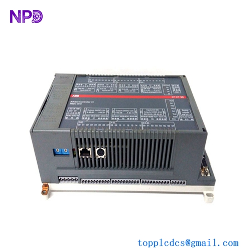
- Model: ABB 3BHB006338R082 UNS 0881A-P V2
- Brand: ABB (Sweden/Switzerland)
- Series: UNS 0881A-P V2 Control Interface PCB
- Core Function: Drive logic and gate driver interface board
- Type: Control Interface / Drive PCB
- Key Specs: Logic-level control interface PCB assembled board Industrial drive integration
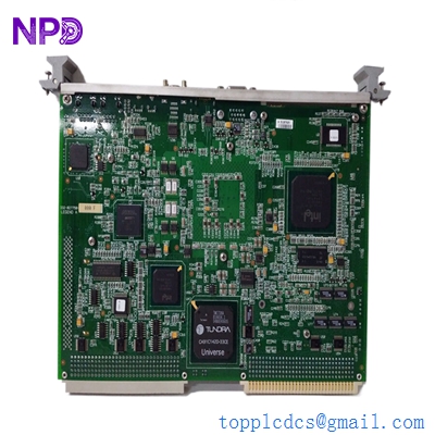
GE VMIVME-7750-746000
Key Technical Specifications
- Part Number: ABB 3BHB006338R082 / UNS 0881A-P V2
- Product Type: PCB assembled control/interface board
- Function: Drive logic / gate driver interface module
- Assembly: Fully populated printed circuit board (PCB)
- Origin: Switzerland (CH) – ABB factory assembly
- Gross Weight: ~0.266 kg (net PCB weight)
- Dimensions: Approx. 320 mm × 230 mm × 37 mm
- Mounting: Internal to drive cabinet / secured on standoffs
- Operating Environment: Installed inside drive enclosure (industrial ambient)
- Warranty: 12 months from shipment (standard)
- Traceability: Serial numbers and manufacturing details retained
Part 4: Installation & Configuration Guide
Important: This is an internal drive control board. Proper handling (ESD safe), accurate labeling, and verified backup procedures are essential. An experienced drive technician or field service engineer should perform replacement.
Phase 1: Pre-Installation (Estimated 15 min)
⚠️ Safety Protocol
- Notify operations and schedule a maintenance window.
- Bring the associated drive and driven equipment to a complete stop.
- Shut down drive power and auxiliary supplies (line and control).
- Discharge capacitors (wait 5–10 minutes).
Tools Required
- ESD wrist strap and mat
- Phillips and flat screwdrivers
- Digital multimeter (Fluke or equivalent)
- Camera for documentation
- Labels for cable identification
Documentation Tasks
- Photograph existing board connections, harness routes, and connector orientations.
- Ensure a control configuration backup is saved in the drive controller memory or external storage.
Phase 2: Removal of Old Interface Board (10–12 min)
- Open drive enclosure carefully and follow lockout/tagout procedures.
- Label all interconnect harnesses attached to the interface board.
- Disconnect wiring connectors one at a time.
- Remove mounting screws/standoffs securing the board.
- Extract board straight out, avoiding twisting or bending.
⚠️ Inspect connectors and harness pins for corrosion or damage before seating the new board.
Phase 3: Installation of New Board (10–15 min)
- Connect ESD protection.
- Confirm new board number: 3BHB006338R082 UNS 0881A-P V2.
- Seat board on standoffs and secure screws.
- Re-connect harnesses according to labeling.
- Double-verify wiring order and harness orientation.
Self-check list:
- Correct board installed
- All connectors fully seated
- Wiring labels matched
- Mounting screws torqued correctly
Phase 4: Power Up & Verification (10–20 min)
Before energizing power:
- Check insulation continuity (no shorts between control low-voltage and chassis ground).
- Confirm supply lines are de-energized.
Power sequence:
- Energize control power first.
- Observe board status indicators (if present).
- Power up drive main supply after verifying control subsystem stability.
- Monitor drive controller for faults.
- Perform basic functional tests (logic response, gate drive enable signals).
Functional check:
- Review drive diagnostics messages.
- Compare with old board fault logs if available.
- Observe fail-safe interlocks and protective responses.
If issues persist after installation, check harness integrity and revisit documentation photos.
Part 5: Customer Cases & Industry Applications
Case 1: Steel Mill AC Drive Control Board Failure
Situation: A steel processing mill’s high-power AC drive developed erratic gate pulse behavior due to internal interface board degradation. Complete drive trips were occurring under load.
Task: Production stoppages caused significant losses. OEM lead time for a new board was quoted at 8–10 weeks.
Action: We supplied a Brand New Surplus ABB 3BHB006338R082 UNS 0881A-P V2 board after ESD-certified testing. Field service replaced the board within a maintenance window.
Result: Drive returned to stable operation without logic faults. Estimated lost production avoided was ~$200,000. The maintenance team added one spare as buffer stock given long lead times.
Case 2: Chemical Plant Strategic Spare Planning
Situation: A chemical processing facility’s variable frequency drives had a history of control board wear due to ambient heat.
Task: With upcoming peak operating season, they could not tolerate drive control board failures. OEM parts backlog was long.
Action: Based on failure trend data, we recommended stocking two interface boards with reorder point set at one and max level at three.
Result: When a board fault occurred weeks later, replacement was immediate — no shutdown delays. Planned buffer stock reduced risk of production loss and expensive expedited freight.
Case 3: Water Treatment Facility Quick Replacement
Situation: A municipal water treatment plant experienced a drive control board fault on a feed pump VFD that controlled critical aeration blowers.
Task: Pump downtime risked violating effluent standards.
Action: We provided a fully tested ABB interface board within 48 hours.
Result: The drive was back in service during a scheduled maintenance shift — compliance requirements met with no regulatory penalties.
Part 6: Frequently Asked Questions (FAQ)
Q1: What exactly is the ABB 3BHB006338R082 UNS 0881A-P V2 board?
A: It’s a drive control/interface printed circuit board (internal to ABB drives), often used as a gate driver or logic interface PCB. It is sold as a Brand New Surplus replacement part.
Q2: Is this board new or refurbished?
A: We supply Brand New Surplus units only — original manufactured boards that have never been powered in the field. Each board is verified to match part number and physical condition.
Q3: Can this board be replaced without recalibration?
A: In most installations, swapping in the same board revision does not require system recalibration. Always document existing harness positions and perform pre- and post-tests to confirm system behavior.
Q4: Do I need ESD precautions when handling this board?
A: Yes. Interface PCBs contain sensitive semiconductor elements. Use an anti-static wrist strap and mat during removal and installation to avoid latent damage.
Q5: Are firmware or software updates required after installation?
A: Typically, no firmware update is needed if the board revision matches the original. If the revision differs (V1 vs V2), verify compatibility with your drive controller documentation.
Q6: How should I stock this part for reliability?
A: Treat it as a less-frequent but high-impact failure part. Suggested min = 1, max = 3 units with reorder point at 1. Buffer stock investment is small compared to drive downtime costs.