
Description
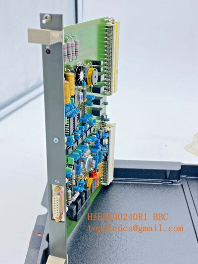
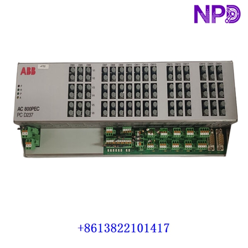
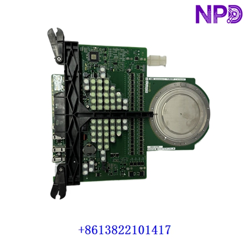
This technical datasheet provides comprehensive specifications, installation procedures, routine maintenance guidelines, troubleshooting steps, safety precautions, and frequently asked questions for the ABB 3BHE019719R0101 controller module PLC hardware incorporating 5SHX 1960L0006 and GV C736 BE101 components. Engineered for high-end industrial automation and power control systems, this high-performance module ensures deterministic processing and reliable real-time system management.

⚙ Product Technical Parameters
- 1. Brand: ABB
- 2. Model: 3BHE019719R0101 / 5SHX 1960L0006 (GV C736 BE101)
- 3. Series: AC 800PEC / Industrial Controller Hardware Series
- 4. Product Name: Programmable Logic Controller (PLC) Processing Module
- 5. Country of Origin: Switzerland / Sweden
- 6. Physical State: High-density surface-mount electronic printed circuit board assembly
- 7. Dimensions: 245 mm × 165 mm × 35 mm (Standard modular rack insert format)
- 8. Weight: 0.85 kg
- 9. Origin Location: European Manufacturing Facility
- 10. Power Consumption: 18W (Max operational draw at rated internal DC rail voltage)
📋 Initial Operation Checklist
Before inserting and powering on the controller module for the first time, verify all physical and electrical configurations to prevent system faults or hardware damage:
- Inspect the enclosure, edge connectors, and optical links for any physical transit damage or dust contamination.
- Confirm that rack backplane power supply voltages and slot keying match the nominal requirements of the module.
- Verify that all communication patch cords, internal bus connectors, and memory cards are firmly locked in place.
- Ensure ambient operating temperature within the control cabinet remains strictly between -10°C and +55°C.
- Check system initialization LED definitions in the engineering manual to prepare for status interpretation during initial boot-up.
🛠 Routine Maintenance and Upkeep
Regular maintenance ensures optimal operational longevity and sustained reliability across high-speed industrial control architectures:
- Perform bi-annual visual checks to ensure cabinet cooling fans are fully functional and air filters are free of obstruction.
- Clean external module faceplates using a dry, anti-static microfiber cloth; strictly avoid liquid solvents, sprays, or abrasive agents.
- Monitor firmware versions and system diagnostic logs periodically during scheduled plant maintenance outages.
- Check backplane mounting screws and terminal connections annually to prevent intermittent contact failure caused by plant vibration.
🔧 Troubleshooting and Common Issues
Systematic problem isolation minimizes downtime when operational anomalies or processing faults occur:
- RUN/FAULT LED Indicates Error: Check system diagnostic registers via the engineering software suite, cycle rack power, and verify firmware compatibility.
- Communication Loss with I/O Subsystem: Inspect optical bus cables, verify network termination settings, and check node address configurations.
- Controller Over-Temperature Alarm: Verify cabinet ventilation clearance, check ambient temperature levels, and inspect internal enclosure cooling fans.
- Intermittent System Resets: Check DC rail voltage stability under load and ensure backplane pins are completely free of oxidation or dust.
🛡 Safety Precautions
Strict adherence to safety guidelines protects personnel from severe electrical hazards and prevents permanent hardware damage:
- Always turn off rack power supplies before inserting, removing, or servicing controller and I/O modules.
- Observe standard electrostatic discharge (ESD) wrist strap protocols when handling electronic printed circuit boards.
- Do not operate the controller unit in explosive or hazardous environments unless housed in a certified explosion-proof cabinet.
- Ensure all system wiring complies strictly with local electrical codes, industrial safety standards, and manufacturer recommendations.
❓ Frequently Asked Questions (Q&A)
- Q1: Can this controller module be replaced while the system is powered on (hot-swapping)?
- A1: Hot-swapping is generally restricted unless specifically supported by the redundant rack configuration and system architecture. Power down the rack slot prior to removal to avoid memory corruption or backplane damage.
- Q2: What should I do if the module fails to boot up after installation?
- A2: Verify that the module is completely pushed into the backplane slot and securely locked. Check input power rails, inspect status indicator lights, and consult the error code log using the programming tool.
- Q3: Is project code backup retained if system power is unexpectedly lost?
- A3: Yes, application logic and configuration parameters are stored in non-volatile flash memory on the module, ensuring user programs are preserved through power interruptions.