Description
- Model: ABB 3BHE023584R2634 (PPD113B03-26-100110)
- Brand: ABB (Switzerland)
- Series: ACS800 / MEGADRIVE-LCI High-Power Drive Control Series
- Core Function: Main processing and control unit for large variable speed drives and excitation systems
- Condition: Brand New Surplus (Original authentic stock, never used, zero refurbishment)
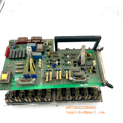
- Product Type: Drive Control Board / Processor Module
- Key Specs: Synchronous serial interface, fiber-optic communication channels, 24 V DC internal logic rail
- Input Operating Voltage: 24 V DC (±10% tolerance window)
- Current Consumption: 1.8 A nominal logic load
- Processor Architecture: High-speed digital signal processor (DSP) with integrated FPGA layer
- Communication Interface: Multichannel fiber-optic links for high-voltage isolation
- Local I/O Configuration: Dedicated fast-response digital inputs for encoder/pulse feedback
- Cooling Requirement: Convection cooled within a sealed cabinet environment
- Operating Temperature Range: 0°C to +55°C (Non-condensing)
- Storage Temperature Limits: -40°C to +70°C maximum
- Humidity Threshold: 5% to 95% relative humidity (RH)
- Coating Specification: Conformal coating for basic atmospheric moisture protection
- Enclosure Rating: IP00 (Open chassis board configuration)
- System Software Compatibility: Requires drive control firmware version 5.0 or higher
ABB 3BHE023584R2634 PPD113B03-26-100110
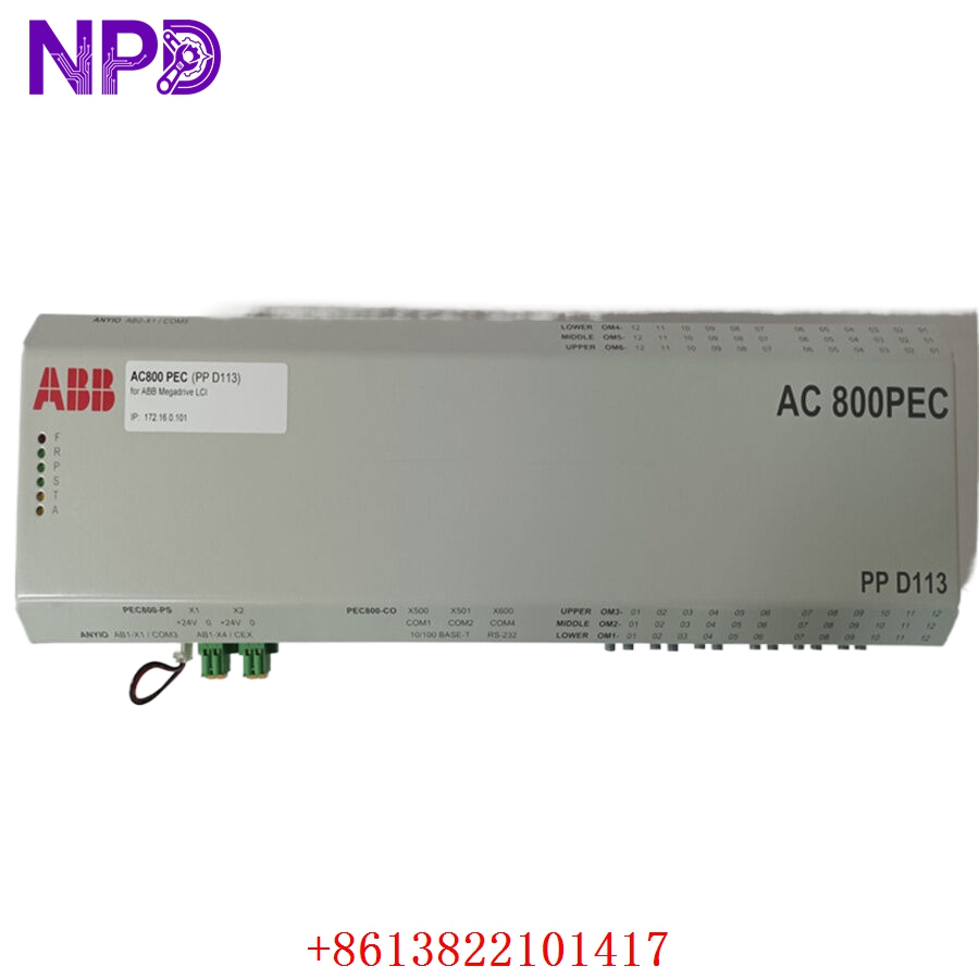
ABB 3BHE023584R2634 PPD113B03-26-100110
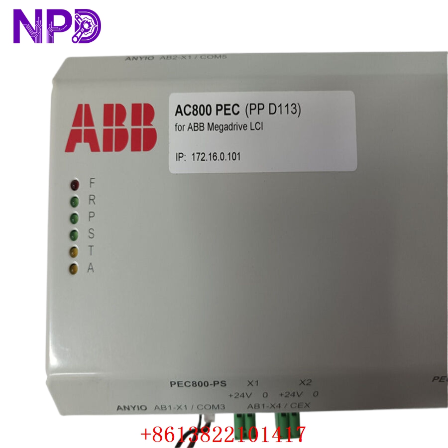
ABB 3BHE023584R2634 PPD113B03-26-100110
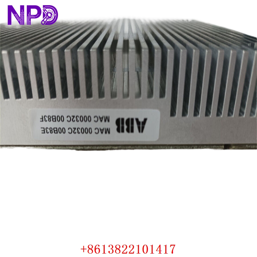
ABB 3BHE023584R2634 PPD113B03-26-100110
Installation & Configuration Guide
Pre-Installation Setup
⚠️ CRITICAL SAFETY WARNING:
- Coordinate a formal shutdown window with the plant operations desk before touching the drive bay.
- Ensure the main incoming medium/low voltage circuit breakers are racked out and tagged.
- Disconnect all auxiliary supplies, including secondary 24 V DC rails and UPS power lines.
- WAIT AT LEAST 15 MINUTES. The intermediate DC bus capacitors hold lethal charges. Use a calibrated meter to verify DC voltage is below 50 V before opening the housing.
- Required Tools & Gear:
- Clean, grounded anti-static wrist strap and an ESD-safe workbench mat.
- Torx T20 and T25 drivers, along with a precision flat-head screwdriver (2.5 mm).
- Digital multimeter (such as a Fluke 87V) with insulated probes.
- Fiber-optic cleaning kit (isopropanol wipes and specialized swabs).
- High-resolution camera or smartphone for structural documentation.
- Backup Procedures:
- Before killing power, connect your laptop via the DriveWindow software tool and pull a full parameter backup (.dcp file).
- Take clear photos of the fiber-optic routing. If you mix up the transmitter (Tx) and receiver (Rx) lines later, the system will face an immediate communication timeout timeout.
- Document all physical hardware selector switches and internal jumper placements on the board face.
Old Board Removal
- Isolate the Fiber Links: Carefully unclip the optical fiber pairs. Label each strand immediately with its matching channel number (e.g., CH0, CH1) using wrap-around wire markers. Fit protective dust caps over the exposed fiber tips.
- Clear the Copper I/O: Unplug the terminal blocks by backing out the side retention screws. Do not tug on individual wires; pull the plastic connector body straight out from the header pin arrays.
- Release Fasteners: Back out the four M4 grounding/mounting screws from the corners of the main PCB chassis. Keep these screws separate, as they maintain the board-to-ground grounding plane.
- Extract safely: Slide the board out from its card-cage guides, handling it only by the fiberglass edges. Never touch any surface-mount components or the back-plane pin headers directly with your bare fingers.
New Board Mounting and Configuration
- ESD Mitigation: Strap on your grounded wristband before tearing open the sealed foil barrier bag. Lay the new board flat across your anti-static work mat.
- Match Hardware Topology: Look closely at your reference photos of the old board. Move the jumper shunts on the new board to replicate the exact same node setup.
- Station Address Identification: Adjust the local DIP micro-switches to match the previous binary address structure.
- Fiber Transceiver Calibration: Confirm whether the optical ports match the specific transmission attenuation level required by your drive layout.
- Chassis Attachment: Slide the board cleanly down the housing guide tracks until the rear connectors align. Press firmly until it bottoms out completely. Thread the four corner screws back in by hand, then torque them down to exactly 1.2 N·m to establish a solid frame ground connection.
- Re-terminate Connections: Clean the fiber ends with your lint-free swabs, then click them firmly into the optical transceivers until they snap home. Plug the copper I/O terminal strips back into place and hand-tighten the retention screws.
Post-Installation Verification Checklist
- [ ] Verify all jumpers match the original site configuration perfectly.
- [ ] Confirm every fiber-optic link is clicked into its correct Tx/Rx channel slot.
- [ ] Check that no loose washers, stray wire strands, or tools are left inside the drive cabinet.
- [ ] Test the electrical resistance between the board ground terminal and the main copper cabinet ground bus bar; it must read less than 0.1 Ω.
Power-Up & Loop Commissioning
- energize the auxiliary 24 V DC supply loop first. Do not throw the main line isolation switch yet.
- Check the surface LED status panel indicators:
- GREEN (POWER / RUN): Solid green means the board is booting properly.
- RED (FAULT): A solid red light means you have a critical hardware mismatch or corrupted boot sequence.
- YELLOW (ALARM): Blinking yellow typically flags an open fiber loop or missing line supply parameters.
- Establish an active link to the drive via your DriveWindow interface tool. Scan the local bus network to confirm that node address matches your configuration. Read and log the factory-flashed firmware version. If the old board used version 5.2 and this one ships with 5.6, you might need to update the parameter map layout to avoid runtime calculation errors.
- Download your archived parameter save file back down to the flash storage on the board.
- Execute a dry run of the software loop: command a low-speed rotation or run an excitation self-test. Check the feedback loops to make sure the encoder pulse reads smoothly across the entire range.
- Once the system runs clean for 30 minutes with zero optical link dropouts, record the serial number into the central maintenance log and clear the unit for normal operations.
Customer Cases & Industry Applications
Case 1: Marine Propulsion Drive Recovery in East Asia
A container vessel equipped with an ABB marine propulsion drive system experienced a sudden deep-sea shutdown due to a main control board failure on its primary active inverter block. The vessel was forced to run on its backup propulsion loop, cutting its cruising speed by half and threatening severe port arrival penalty fees.
The fleet maintenance supervisor found our listed stock for this component while the ship was still moving toward port. We pulled the board from our warehouse, mounted it to our dedicated test rack, and ran a continuous 24-hour heat cycle simulation. The certified test report and functional video clips were uploaded to the ship’s agent for verification before the vessel even made landfall. The package was waiting at the customs dock when the ship arrived. Shipboard electrical engineers swapped the board out in under two hours using the on-board parameter backup. The drive started up without any communication issues, allowing the vessel to hit its next scheduled port window on time.
Case 2: Steel Rolling Mill Drive Life Extension
A heavy plate rolling mill in the Midwest relied on a legacy variable speed system to run its main reversing mill motor. The drive control unit started throwing sporadic fiber-optic link errors, causing sudden mill trips that warped steel sheets in progress. Each hour of unplanned down-time cost the facility more than $15,000 in ruined raw materials and idle operator labor.
The original manufacturer declared this specific controller configuration obsolete, offering an upgrade path to their newest drive series. However, that transition would require a total engineering redesign, new control cabinets, and a full two-week plant shutdown, costing an estimated $320,000. The mill operators needed an alternative to keep the line running for another three years until their next scheduled capital overhaul. They bought two new surplus units from us to secure an instant on-site backup strategy. Replacing the failing board instantly stabilized the signal paths, dropping line faults back to zero. This move protected their capital budget and successfully kept their existing assets running without a major upgrade project.
Frequently Asked Questions (FAQ)
Q1: What exactly does “New Surplus” mean for this specific board? Is it a pulled or repaired item?
A: Let’s clear that up right away: this board is completely new and has never been installed in a live machine. It is clean surplus inventory sourced from canceled engineering projects or excess plant reserve stock. It is not an item pulled from a working machine, it is not a repaired board, and it has never seen service hours. The circuit card shows no component degradation, no slot wear on the connector keys, and no track alterations. We keep it stored in a climate-controlled room wrapped in a heavy ESD foil barrier to prevent component degradation.
Q2: If the board is already new, why do you perform an extra live test?
A: We treat every high-power component we sell as a critical insurance policy for your operation. Even pristine factory boards can develop subtle issues if they sit in a warehouse for an extended period—silicon junctions can age, and internal software versions need validation. To protect your equipment, we run every unit through a strict quality protocol:
[Inbound Traceability Check]
       │
       ▼
[Visual Inspection under Magnification]
       │
       ▼
[Functional Rack Test & Fiber Loop Verification]
       │
       ▼
[24-Hour Thermal Load Burn-in]
       │
       ▼
[Final Engineering Sign-Off & Certified Test Report]
We do not ship a part unless it passes every single stage of this checklist. If you need documentation for your internal quality team, we can send you full video clips and photos of your specific board on our test bench before boxing it up.
Q3: Can I swap this unit directly out with an older version of the board?
A: No, you need to verify your existing hardware layout first. While the base design is highly compatible across similar drive frames, the specific suffix numbers indicate the exact hardware revision level and the firmware build loaded at the factory.
| Model Variant | Internal Processing Hardware | Backplane Speed | Firmware Compatibility |
| PPD113B03-26-100110 | High-performance DSP core | Enhanced baud rate | Version 5.0 and above |
| PPD113B01 / Older variants | Legacy controller chipsets | Base line speed | Version 3.x or 4.x only |
If you attempt to replace an older version with this model without updating your system architecture, the drive processor will likely throw an initialization error or block parameter downloads. Feel free to send us a photo of your existing cabinet nameplate, and our team will check the physical compatibility for you.
Q4: What happens if the module fails to boot after installation?
A: In our experience, about 90% of initial startup issues stem from an incorrect node address configuration or a broken fiber optic connector clip. If your run light fails to turn green, step through these quick troubleshooting checks:
- Verify the binary value on the micro-DIP switch assembly exactly matches your old board’s address.
- Check the fiber ports under a magnifying lens to ensure no dust particles are blocking the light path.
- Use a multimeter to confirm the local power supply is delivering a stable 24 V DC directly to the terminal input.
If the board still shows a hard system fault after verifying these steps, contact our support line immediately. We provide a full 1-year replacement warranty. If our engineers confirm a hardware defect on the board, we will arrange an express advance replacement from our stock to keep your downtime to an absolute minimum.
Q5: Do your listed prices include localized import duties or VAT for international shipments?
A: Our standard product quotes are provided on an Ex-Works (EXW) or Delivered Duty Unpaid (DDU) basis. This means the base price covers the component and our specialized export packing, but does not include your local taxes, processing fees, or import tariffs. If your corporate purchasing workflow requires an all-inclusive price, just let us know before placing the order. We can calculate your local customs charges and provide a Delivered Duty Paid (DDP) quote, allowing you to pay the full balance upfront and avoid customs delays.