
Description
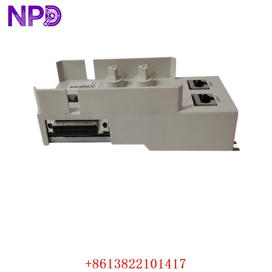
- Model: ABB 3BSE018126R1 TP853
- Brand: ABB
- Series: AC 800M / System 800xA
- Core Function: Communication module mounting and signal interface
- Product Type: Module Termination Unit / Baseplate
- Key Specs: Supports CI853/855/857/861, dual RJ45 ports, DIN rail mounting
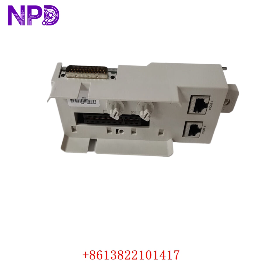
The TP853 baseplate is one of those components engineers often overlook until a communication module replacement is needed. It acts as the electrical and mechanical interface for ABB communication modules inside AC800M and System 800xA environments.
Typical applications include:
- Power generation DCS cabinets
- Petrochemical process systems
- Water treatment SCADA systems
- Pulp & paper automation lines
- Marine propulsion control systems
Even though it looks mechanically simple, a damaged or oxidized baseplate can create intermittent communication failures that are painful to troubleshoot. In real-world maintenance work, those “random communication alarms” often trace back to worn connectors or damaged terminal bases rather than the communication card itself.
For inventory planning:
- Critical process plants should keep 1–2 spare TP853 units
- Multi-site groups can share buffer stock centrally
- Slow-moving facilities may prefer vendor-managed inventory
Because this part supports mature AC800M infrastructure, many operators now adopt a last-time-buy strategy before surplus inventory tightens further.
Key Technical Specifications
- Product ID: 3BSE018126R1
- ABB Type Designation: TP853
- Product Type: Module Termination Unit / Baseplate
- Compatible Modules: CI853, CI855, CI857, and CI861
- Compatible Systems: ABB AC800M and System 800xA
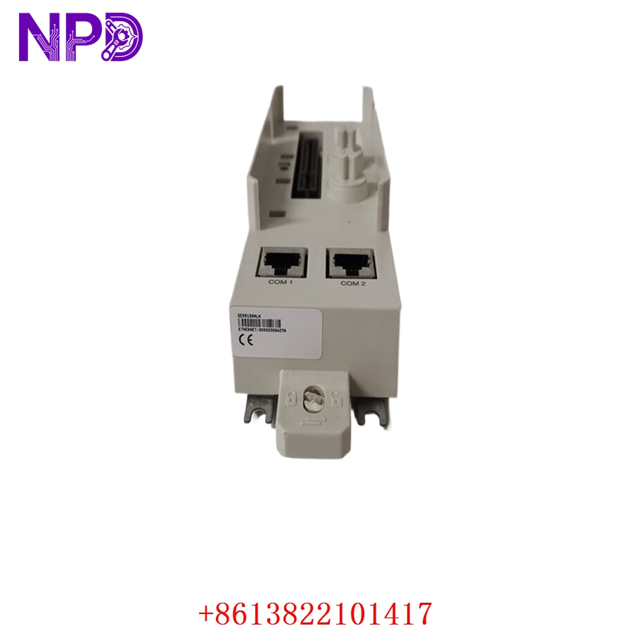
- Ethernet Ports: Dual RJ45 connectors
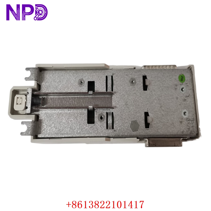
- Mounting Method: DIN rail or panel mounting
- Operating Voltage: 24 V DC
- Current Consumption: Approximately 150 mA
- Dimensions: 162 mm × 63 mm × 45 mm
- Net Weight: Approximately 0.5 kg
- Operating Temperature: -20 °C to +60 °C
- Humidity Range: 5–95% non-condensing
- Material Type: Industrial-grade composite with conductive connectors
- Protection Features: Mechanical keying and module code lock
- Country of Origin: Sweden / United States
- Communication Support: Ethernet-based industrial communication integration
Technical information compiled from industrial automation references and ABB spare-part listings.
Installation & Configuration Guide
Pre-Installation Preparation (Estimated Time: 10 Minutes)
⚠️ Safety First
- Notify operations before maintenance begins
- Confirm the controller can tolerate communication interruption
- Switch the process to a safe operating condition
- Isolate cabinet power if required
- Wait at least 5 minutes for internal discharge
Required Tools:
- Anti-static wrist strap
- PH1 screwdriver
- Fluke 115 multimeter
- Label markers
- Ethernet cable tester
- Mobile phone or camera
Before removal:
- Photograph existing communication wiring
- Record module slot arrangement
- Save IP configuration and node information
- Check controller redundancy status
Honestly, communication baseplates are easy to underestimate. Engineers often replace the CI module first, only to discover the backplane connector itself caused the fault.
Removing the Existing TP853 (Estimated Time: 5 Minutes)
- Disconnect Ethernet cables carefully
- Label network ports before removal
- Remove attached communication module
- Release DIN rail latch
- Pull baseplate vertically from mounting rail
Inspect carefully:
- RJ45 connector wear
- Bent pins
- Corrosion traces
- Heat discoloration
- Mechanical cracks
⚠️ Important:
Do not twist the baseplate during removal. Excessive side force can damage adjacent communication modules or DIN rail clips.
Installing the New Module (Estimated Time: 10 Minutes)
- Wear anti-static protection
- Open anti-static packaging carefully
- Verify exact model number: TP853 / 3BSE018126R1
- Inspect connector surfaces
- Mount baseplate securely onto DIN rail
- Install compatible CI communication module
- Restore Ethernet connections
Critical checks:
- Correct communication module type
- Proper grounding
- Secure RJ45 locking
- Redundancy cable routing
- No stress on Ethernet cables
Installation checklist:
- DIN rail fully locked
- Communication module seated correctly
- Ethernet ports labeled
- Shield grounding verified
- Cabinet clearance confirmed
- No loose hardware inside enclosure
Power-On & Functional Testing (Estimated Time: 15 Minutes)
Before energizing:
- Verify 24 V DC supply stability
- Check grounding continuity
- Confirm Ethernet cable integrity
Power-up procedure:
- Energize communication cabinet
- Observe module status LEDs
- Verify network link activity
- Open Control Builder or 800xA engineering tools
- Confirm communication handshake
- Verify controller diagnostics
Functional tests:
- Ethernet communication verification
- Network redundancy switching test
- Module recognition test
- Alarm monitoring
- Communication polling stability
Our incoming QC process normally includes:
- Original label verification
- Serial number documentation
- Mechanical fit inspection
- Ethernet continuity testing
- Connector retention testing
- 24-hour communication stability verification
We also archive:
- DIP switch photos
- Module compatibility records
- Test bench screenshots
- QC inspection reports
Test videos and inspection photos can usually be provided before shipment.
Customer Cases & Industry Applications
Case 1: Petrochemical DCS Communication Failure Recovery
A petrochemical facility in East Asia operated an ABB AC800M system controlling several reactor units. Operators started seeing intermittent Ethernet communication losses between redundant controllers and field communication modules.