Description
- Model: 560CMU05
- Ordering Code: 1KGT012700R0005
- Brand: ABB (Grid Automation / Hitachi Energy)
- Series: RTU560 (Remote Terminal Unit)
- Core Function: Communication Unit (CMU) and Controller for the RTU560 sub-rack
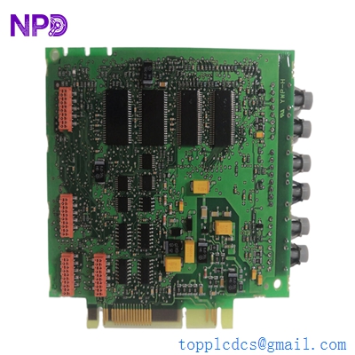
- Product Type: Central Processing Unit / Communication Board (New Surplus)
- Key Specs: 2x Ethernet ports | 4x Serial ports | Integrated real-time clock | Web-based configuration
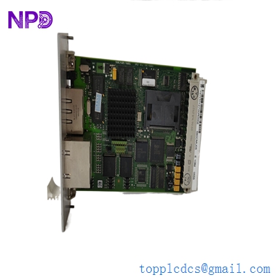
ABB 560CMU05
Key Technical Specifications
- Module ID: 560CMU05
- Hardware Revision: Compatible with R0005 standards
- Processor: High-performance 32-bit RISC controller
- Interfaces:
- Ethernet: 2x 10/100 BaseT (RJ45) for WAN/LAN connectivity
- Serial: 4x RS-232/RS-485 configurable interfaces for sub-device polling
- Protocols Support: IEC 60870-5-101/104, DNP3, Modbus (RTU/TCP), IEC 61850
- Storage: Onboard Flash memory for firmware and site configuration
- Diagnostics: Integrated LEDs for System, LAN, and Serial link status
- Sub-rack Compatibility: Fits into any RTU560 sub-rack (560MPR03, 560SFR02)
- Power: Powered via the sub-rack backplane (+5 V DC)
- Isolation: Reinforced galvanic isolation on all serial communication ports
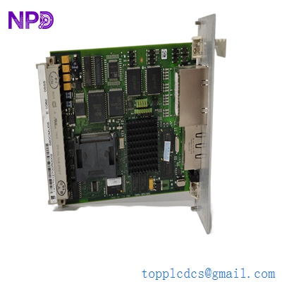
ABB 560CMU05
Installation & Configuration Guide
Phase 1: Preparation (Pre-Installation)
⚠️ Safety First:
- Ensure the RTU560 sub-rack power supply is turned off before module insertion.
- Backup: Use the RTUtil560 software to take a full backup of the current project configuration.
- ESD Protocol: Use a grounded wrist strap. The 560CMU05 contains high-density flash memory sensitive to static.
Phase 2: Removal of Faulty Module
- Labeling: Mark all Ethernet and Serial cables. The serial ports (CP1–CP4) often use different protocols; swapping them will cause immediate telemetry loss.
- Ejection: Release the screw fasteners on the front panel and use the pull-levers to slide the board out of the rack card guides.
- Internal Jumpers: Check the side of the board for any hardware jumpers used for RS-232/RS-485 selection. Match these on the new board.
Phase 3: New Module Installation
- Firmware Check: Verify the firmware version of the new 560CMU05. It should match the other CMUs in the rack if you are running a redundant configuration.
- Seating: Slide the module into the designated slot. Ensure the 96-pin connector on the backplane is fully engaged.
- Cabling: Reconnect the LAN and Serial cables. Ensure the RJ45 connectors click firmly into place.
Phase 4: Commissioning & Testing
- Boot Sequence: Power up the rack. The “ST” (Status) LED should transition from red to green after the initialization sequence.
- Web Interface: Connect a laptop to the LAN port and access the integrated web server. Verify that the CPU load and memory usage are within normal limits.
- Project Download: Use RTUtil560 to download the site-specific configuration file to the flash memory of the new module.
- Link Check: Monitor the “Rx/Tx” LEDs on the front panel to confirm that data polling to IEDs (Intelligent Electronic Devices) has resumed.
ABB 560CMU05
Customer Cases & Industry Applications
Case 1: Restoring Scada Comms at a High-Voltage Substation
Situation: A 220kV substation in Australia lost its primary link to the Load Dispatch Center (LDC). The RTU560 reported a “Processor Failure” on the main 560CMU05 module, leaving the LDC blind to the substation’s switchgear status.
Task: The utility required an immediate replacement to maintain grid stability. ABB’s local lead time was quoted at 6 weeks. The utility needed a “zero-hour” part that could handle the harsh, electrically noisy environment of a switchyard.
Action: We supplied a New Surplus 560CMU05 from our stock. It was dispatched via express air freight and reached the site in 3 days.
Result: The field engineer uploaded the backup configuration via the web interface, and the IEC 104 link to the SCADA system was restored within an hour of the part arriving on site. The utility subsequently upgraded their spares inventory with two additional units from us.
Case 2: Redundancy Upgrade for a Renewable Energy Farm
Situation: A large-scale solar farm used a single-controller RTU560 setup. They experienced an intermittent “Watchdog Reset” on their aging CMU board, which risked losing critical power generation data.
Task: The farm manager decided to move to a redundant CPU configuration (Dual CMUs) to ensure 99.99% uptime for their reporting. They needed an identical 1KGT012700R0005 to match their existing hardware revision.
Action: We provided a revision-matched 560CMU05. Because our parts are New Surplus, the internal real-time clock battery and flash memory were in pristine condition.
Result: The solar farm successfully implemented the redundant failover strategy. The plant now operates with two active-standby CMUs, providing the security needed for their PPA (Power Purchase Agreement) compliance.
Frequently Asked Questions (FAQ)
Q: Is the 560CMU05 compatible with the older RTU560 CMUs? A: The 560CMU05 is the successor to the CMU02. It offers more memory and faster processing. While it fits the same sub-racks, you must ensure your RTUtil560 project is updated to recognize the new hardware type before downloading the configuration.
Q: Does the module come with pre-installed protocols? A: The hardware supports a wide library of protocols (IEC 101/104, Modbus, etc.), but these must be activated via the license and configuration file during the setup process.
Q: Why choose New Surplus over refurbished? A: In grid automation, reliability is everything. Refurbished boards have already endured years of heat and power cycles. New Surplus boards have sat in a box; their electrolytic capacitors and flash chips haven’t aged, leading to a significantly higher MTBF (Mean Time Between Failures).
Q: Can I use the Ethernet ports for a redundant ring? A: Yes, the dual Ethernet ports on the 560CMU05 can be configured for network redundancy (PRP/HSR or simple line redundancy) depending on your firmware version and network switch setup.
Q: How do I know if the board is healthy? A: The “ST” LED is your primary indicator. Green means “OK,” Red means “Fatal Error,” and Blinking Red/Green usually indicates the module is in “Bootloader” mode waiting for a firmware or configuration download.