
Description
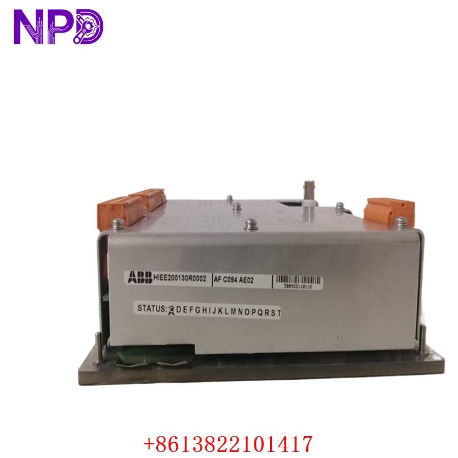
- Model/Type Designation: ABB AFC094AE02
- Product ID/Part Number: HIEE200130R0002
- Brand: ABB (Asea Brown Boveri)
- System Control Architecture: ABB Variable Frequency Drive (VFD) Auxiliary Control / Medium-Voltage Drive Interface Frameworks.
- Core Function: Specialized auxiliary control and I/O interface board. It serves as a secondary processing node or signal routing bridge within the drive’s control cabinet, managing auxiliary I/O loops, status feedback telemetry, and low-voltage logic synchronization between the drive’s main processor and secondary external control panels.
- Operating Input Voltage: 24 V DC internal logic rail feed
- Signal Handling: Multi-channel auxiliary digital input/output routing
- Input Isolation: Optocoupler isolation across all digital interface lines for ground-loop noise rejection
- Processing Logic: Onboard programmable signal conditioning and status telemetry logic
- Communication Interface: High-speed internal bus connector for integration with the main drive control processor
- Operating Ambient Temperature: -20°C to +70°C maximum control cabinet environment limits
- Storage Temperature Window: -40°C to +85°C structural envelope limits
- Atmospheric Moisture Limits: 5% to 95% relative humidity (RH, non-condensing)
- Mounting Configuration: Designed for direct integration into ABB drive control chassis card files
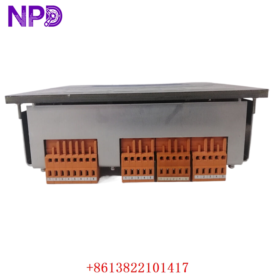
ABB HIEE200130R0002 AFC094AE02
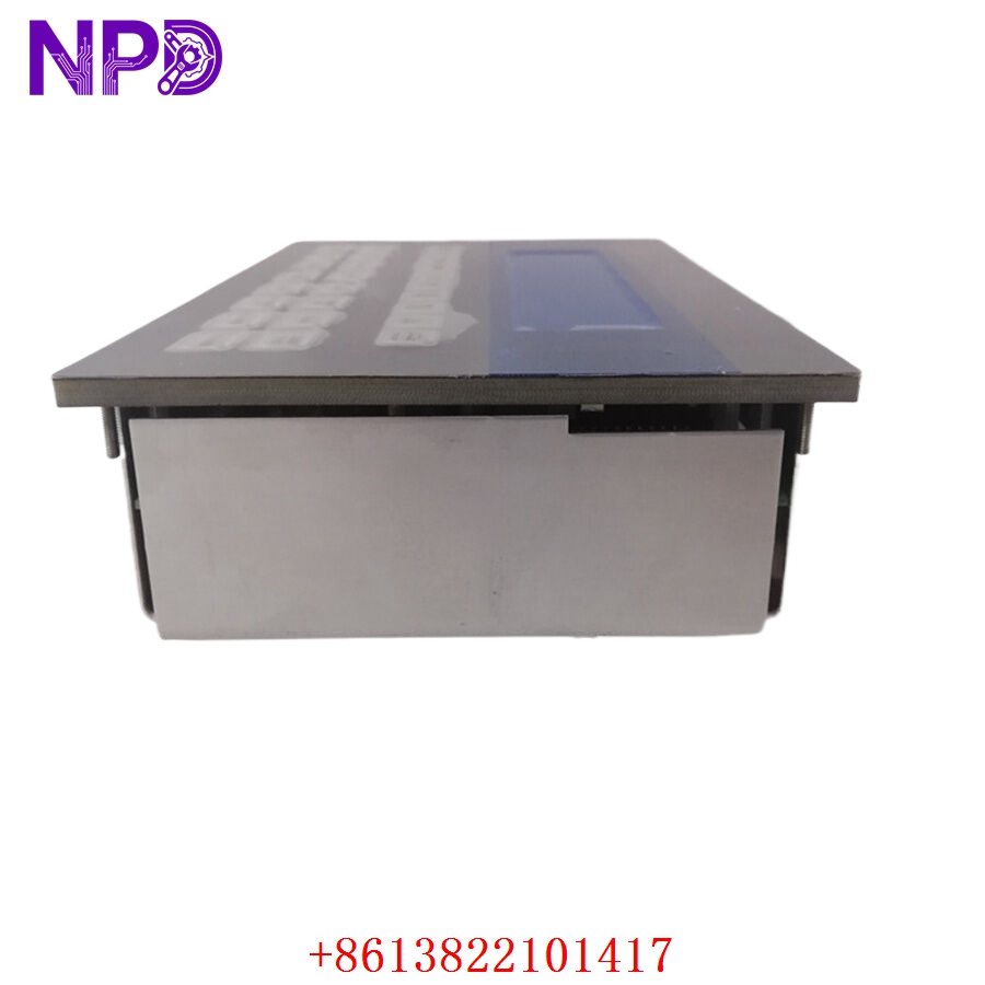
ABB HIEE200130R0002 AFC094AE02
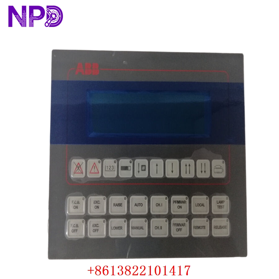
ABB HIEE200130R0002 AFC094AE02
Installation & Configuration Guide
Pre-Installation Setup
⚠️ CRITICAL SAFETY WARNING:
- Coordinate a comprehensive bypass profile with the master operations safety supervisor. Removing an auxiliary control card while energized can cause an unexpected drive state transition, trip high-voltage breakers, and stop heavy rotating machinery.
- DANGER: HIGH VOLTAGE LETHAL RISK. Isolate and lock out (LOTO) all main multi-kilovolt power lines feeding the variable frequency drive. Verify that all DC link bus capacitors are fully discharged.
- Verify proper cabinet grounding to protect sensitive logic components from electromagnetic interference (EMI).
- Required Tools & Gear:
- Grounded anti-static wrist strap anchored to the local cabinet frame.
- Standard 4.5 mm flathead screwdriver and Pozidriv PZ1 tool array.
- Windows engineering laptop running the ABB drive management software suite.
- Backup Procedures:
- Connect to the active drive controller and download a full parameters backup file. This ensures your drive logic configuration is preserved if the auxiliary board holds volatile status mapping.
- Document the physical position of all ribbon cables and jumper settings on the legacy module.
Old Board Removal
- Verify Power Isolation: Confirm all high-voltage isolators are locked out and DC link bus capacitors are discharged.
- Label and Disconnect Wiring: Carefully label and unplug all ribbon cables, optical lines, and terminal block plugs linked to the board’s faceplate.
- Loosen Retaining Hardware: Back out the captive screws securing the control board to the chassis mounting plate.
- Extract Board: Carefully lift the board from its alignment rails, ensuring no contact with adjacent modules. Place the module immediately onto an ESD-protected surface.
New Board Mounting and Configuration
- ESD Mitigation Check: Wear a grounded anti-static wrist strap before opening the protective shielding of the new AFC094AE02 / HIEE200130R0002 board.
- Replicate Onboard Settings: Check any jumpers or switches on the replacement board to ensure they match the original module’s configuration.
- Position in Chassis: Align the board with the chassis mounting standoffs inside the drive control section.
- Secure Fasteners: Tighten the board’s retaining screws to establish a solid frame ground connection.
- Reconnect Data Links: Reattach the cables and plugs into their corresponding ports, ensuring all connector clips click securely.
Post-Installation Verification Checklist
- [ ] Verify all jumper and switch positions match the original card layout.
- [ ] Confirm structural faceplate mounting screws are tightened to ground the module frame.
- [ ] Check that all terminal plugs and ribbon cables are fully seated.
- [ ] Ensure adjacent processing cards remain correctly aligned in the chassis.
Frequently Asked Questions (FAQ)
Q1: What is the relationship between HIEE200130R0002 and AFC094AE02?
A: Model AFC094AE02 is the functional designation for this auxiliary control interface card, while HIEE200130R0002 is the unique ABB manufacturing product ID. Both identify the same physical hardware module.
Q2: How do you verify the functionality of the auxiliary circuits before shipping?
A: We place every surplus module into an authentic ABB drive test chassis. We perform a 24-hour stress test, simulating digital input/output signal sequences to verify that all optocouplers and routing logic operate within factory specifications before the board leaves our facility.
Q3: Does this board require external software programming?
A: No. This module is hardware-driven. It inherits its auxiliary I/O mapping from the main drive controller’s configuration file. Once installed, it automatically functions based on the pre-existing logic established in the drive’s parameters block.
Q4: What do diagnostic LEDs on the module faceplate indicate?
A: Typically, green LEDs indicate healthy logic power and active bus communication. If you observe red or amber status lights after installation, verify that the board is fully seated in its chassis and that all configuration parameters in the drive control software correctly recognize the module.
Q5: What payment and shipping methods do you offer for urgent emergency plant shutdowns?
A: We accept international wire transfers (T/T), corporate credit cards, and standard letters of credit. For emergency repairs during an unplanned outage, send over a copy of your bank’s wire transfer confirmation slip. Our logistics team will immediately pull the part from our stock, complete our quality verification testing, and hand it off to an express air courier (like DHL or FedEx) to minimize your facility’s downtime.