Description
Product Overview
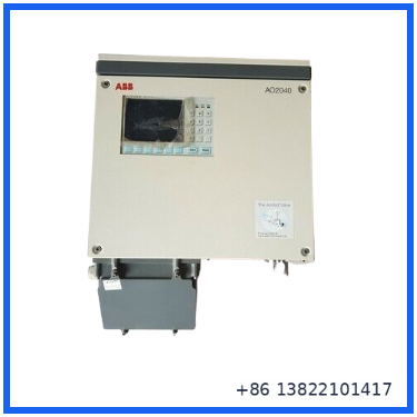
The ABB AO2040 is a wall-mounted version of the Advance Optima AO2000 series modular continuous gas analyzer platform. It is designed for continuous measurement of process gases and can be configured with different analyzer modules according to the application.
Unlike a single-purpose portable gas detector, the AO2040 is a complete analyzer platform with a system controller, display and operating unit, power supply, and analyzer module arrangement. Additional external analyzer modules can also be integrated into the system.
The specific unit in the referenced listing is identified as AO2040, with a 100–240 VAC, 50/60 Hz input and maximum input current of 2.2 A. The listing also specifies a +24 V / 4 A output. The item is listed as New – Open box.
Product Summary
ABB AO2040 belongs to the Advance Optima family of modular continuous gas analyzers.
The platform can accommodate different analyzer principles and modules, allowing the same basic system architecture to be used for different process-gas measurement requirements. ABB documentation lists analyzer modules such as Uras26, Limas21, Magnos206, Caldos25, Caldos27, Fidas24 and other modules within the AO2000 family.
The AO2040 wall-mounted housing measures approximately 444 mm wide × 199 mm deep × 412 mm high for the basic housing, with additional height depending on the connection-box configuration. ABB specifies IP20 for the basic housing, IP54 with connection box, and IP65 for configurations without the power supply/display and control unit.
Product Datasheet
| Parameter | Specification |
|---|---|
| Brand | ABB |
| Model | AO2040 |
| Product Family | Advance Optima AO2000 Series |
| Product Type | Continuous Gas Analyzer |
| Installation | Wall-mounted |
| Input Voltage | 100–240 VAC |
| Input Current | Max. 2.2 A |
| Frequency | 50/60 Hz |
| Listed Output | +24 VDC / 4 A |
| Housing Width | Approx. 444 mm |
| Basic Housing Depth | Approx. 199 mm |
| Basic Housing Height | Approx. 412 mm |
| Housing Protection | IP20; IP54 with connection box; IP65 in specified configuration |
| Analyzer Architecture | Modular |
| Additional Analyzer Modules | Supported |
| Country of Origin | Germany |
| Listed Weight | Approx. 15.67 kg |
| Listing Condition | New – Open box |
The electrical input values above match both the supplied eBay listing and ABB’s published AO2040 specifications. The actual analyzer measuring range and gas components depend on the analyzer module(s) installed in the particular unit.
Modular Analyzer Architecture
One of the main characteristics of the Advance Optima platform is its modular design.
The AO2040 system can be configured around different measuring principles rather than being restricted to one gas or one measurement method. This makes the platform suitable for process applications where the required gas components or measurement technology may change between installations.
Depending on the installed configuration, the AO2000 family includes analyzer technologies such as:
- Infrared gas measurement
- UV measurement
- Paramagnetic oxygen measurement
- Thermal conductivity measurement
- Flame ionization measurement
Examples of ABB analyzer modules include Uras26, Limas21, Magnos206, Caldos25, Caldos27 and Fidas24. Not every AO2040 contains the same analyzer module, so the installed module identification should be checked before specifying the measurable gas components or range.
Power Supply
The AO2040 system is designed for a wide AC input range.
The published electrical specification is:
Input: 100–240 VAC
Frequency: 50–60 Hz
Maximum input current: 2.2 A
The AO2000 central-unit power supply generates 24 VDC for the electronics and one analyzer module installed in the central unit or one external analyzer module. ABB documentation specifies a 24 VDC output and maximum power consumption around 187 W for the central-unit power supply configuration.
The exact power requirements of the complete analyzer depend on the analyzer modules and options installed.
Housing and Installation
The AO2040 uses a wall-mounted housing.
ABB’s published dimensions for the basic AO2040 housing are approximately:
444 mm W × 199 mm D × 412 mm H
A connection box can increase the overall height to approximately 597 mm. Clearance is also required for opening the enclosure door and for connecting process, electrical and signal lines.
For installations with heated sample-gas connections, additional clearance may be required to accommodate the specified minimum bend radius of the heated line. ABB also notes that certain MultiFID14 configurations require additional access space above the analyzer.
Housing Protection
The protection rating depends on the actual housing configuration.
| Configuration | Protection |
|---|---|
| Basic AO2040 housing | IP20 |
| With connection box | IP54 |
| Without power supply and display/control unit, specified configuration | IP65 |
The protection rating should therefore not be advertised simply as IP65 for every AO2040 configuration. The installed options and housing arrangement determine the applicable rating.
Typical Application Areas
The AO2040 is intended for continuous process-gas analysis rather than occasional field sampling.
Typical applications include:
- Combustion-process monitoring
- Emission monitoring
- Industrial process control
- Chemical processing
- Power generation
- Refining and petrochemical processes
- Steel and other heavy industries
- Environmental gas monitoring
- Process optimization
- Continuous gas-quality measurement
The appropriate analyzer module, sample conditioning system and measurement range must be selected according to the gas composition and process conditions.
Installation Considerations
Before installation, verify the complete analyzer configuration rather than relying only on the AO2040 model number.
Check:
- Installed analyzer module type.
- Gas components being measured.
- Measurement ranges.
- Sample-gas inlet and outlet connections.
- Required sample pressure and flow.
- Sample conditioning requirements.
- Power-supply configuration.
- Signal and communication connections.
- Housing protection requirements.
- Required ventilation and installation clearance.
For a replacement unit, photograph and record the existing analyzer-module labels, wiring, tubing connections and configuration before removing the original equipment.
Sample Gas Handling
The analyzer itself is only one part of a complete process-gas measurement system.
Stable measurement depends on the sample-gas system being correctly designed. Depending on the application, the installation may require filtration, pressure regulation, flow control, heating, condensation control and other sample-conditioning equipment.
Particular attention should be paid to moisture and condensation when the sample contains water vapor or when the sample line temperature can fall below the gas dew point.
The correct sample-gas conditions should be determined from the installed analyzer module and the actual process.
Configuration and Commissioning
After mechanical installation, commissioning should normally include:
- Power verification
- Grounding verification
- Analyzer-module identification
- Sample-line leak check
- Sample flow verification
- Zero-gas check
- Calibration-gas check
- Measurement-range verification
- Alarm/status verification
- Analog-output verification
- Communication verification where installed
- Final measurement validation
Calibration should use gases appropriate to the installed analyzer module and the required measurement range.
Maintenance
Routine maintenance depends heavily on the installed analyzer module and sample-conditioning system.
Recommended checks include:
- Inspect sample tubing and fittings.
- Check for gas leaks.
- Check filters and condensate traps.
- Verify sample flow.
- Inspect heated sample lines where installed.
- Check calibration gas quality.
- Review analyzer diagnostic messages.
- Inspect electrical connections.
- Keep the housing and ventilation areas clean.
- Verify zero and span calibration at the required intervals.
If the analyzer is used for emission or regulatory measurement, maintenance and calibration intervals should follow the applicable site procedure and measurement standard.
Replacement Guidance
When replacing an AO2040 in an existing installation, the most important point is to match the complete analyzer configuration.
The AO2040 designation identifies the system housing/platform, but it does not by itself tell you which gas components are measured.
Before purchasing a replacement, compare:
- AO2040 model
- Analyzer module type
- Module part number
- Hardware revision
- Firmware/software configuration
- Measurement range
- Gas components
- Sample connections
- Power configuration
- I/O configuration
- Communication options
- Connection-box configuration
Two AO2040 units can therefore look similar while having different measurement functions.
Inspection Before Shipment
For this type of analyzer, inspection should cover both the electrical hardware and the gas-analysis section.
Recommended inspection points:
- Confirm AO2040 model marking.
- Photograph the complete nameplate.
- Record analyzer-module part numbers.
- Record hardware/firmware information where available.
- Inspect the display and operating controls.
- Check connectors and terminal areas.
- Inspect PCB assemblies for corrosion or contamination.
- Inspect sample-gas fittings.
- Check tubing and seals.
- Inspect the power supply.
- Verify input voltage configuration.
- Perform power-up testing where the required test equipment is available.
- Check analyzer diagnostics.
- Perform calibration/measurement testing where appropriate.
Condition
The specific eBay item supplied for reference is listed as New – Open box. eBay defines this condition as an item in excellent/new condition with no functional defects, although original packaging may be missing and the unit may have been used for testing or demonstration. The listing specifies Germany as the country of origin and approximately 15.67 kg shipping/item weight.
FAQ
What is the ABB AO2040?
The AO2040 is the wall-mounted version of ABB’s Advance Optima AO2000 modular continuous gas analyzer platform.
What is the input power?
The AO2040 is specified for 100–240 VAC at 50/60 Hz, with maximum input current of 2.2 A.
What is the output?
The referenced listing specifies +24 VDC / 4 A. The AO2000 central-unit power supply provides 24 VDC to the electronics and a supported analyzer module.
Which gases can the AO2040 measure?
That depends on the analyzer module installed. The AO2000 family supports several analyzer technologies and modules, so the AO2040 model number alone is not enough to determine the measurable gas components.
Is AO2040 wall mounted?
Yes. ABB identifies AO2040 as the wall-mounted version of the Advance Optima AO2000 platform.
Can an AO2040 be used as a replacement for an existing analyzer?
Potentially, but the analyzer-module configuration must match the existing application. The model number alone should not be used to confirm a drop-in replacement.
Search Terms
ABB AO2040, ABB Advance Optima AO2040, ABB AO2000 Gas Analyzer, ABB Continuous Gas Analyzer, ABB Process Gas Analyzer, Advance Optima Continuous Gas Analyzer, AO2040 Analyzer, ABB AO2040 100-240VAC, ABB AO2040 2.2A, ABB AO2040 50/60Hz, ABB Uras26, ABB Limas21, ABB Magnos206, ABB Caldos25, ABB Caldos27, ABB Fidas24, ABB Process Analyzer, ABB Gas Analysis System