
Description
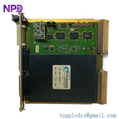
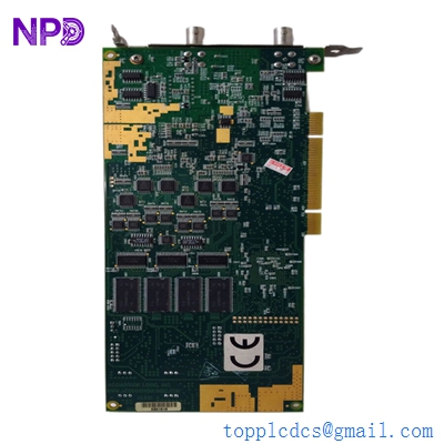
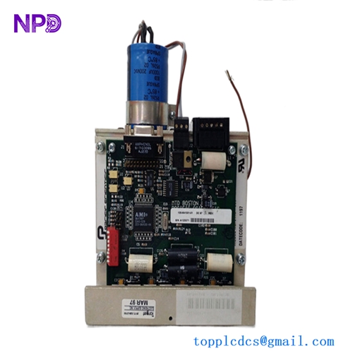
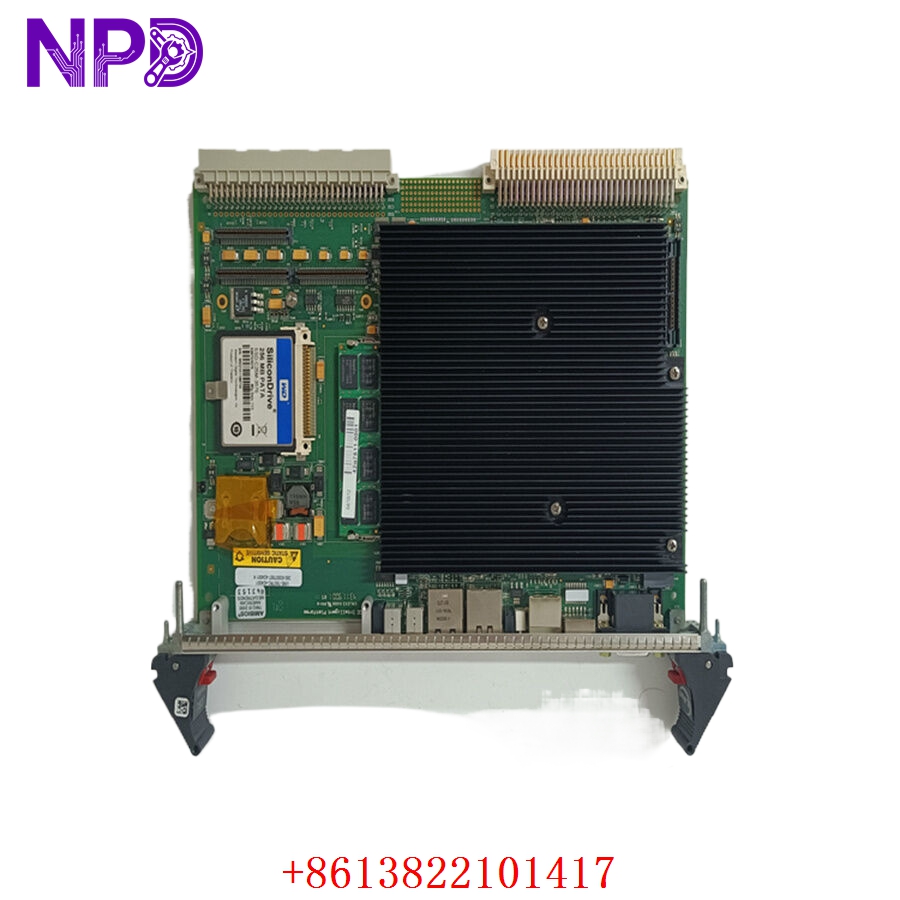
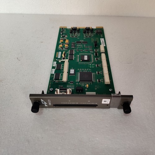
The ABB BAILEY INNIS21 is a high-performance Network Interface Module (NIM) designed for the Bailey INFI 90 and Symphony distributed control systems. This module acts as the critical communication bridge between the local Controlway (the module bus) and the INFI-NET communication network. It ensures seamless, high-speed data exchange between process controllers, operator stations, and other plant-wide automation assets, maintaining real-time reliability for complex industrial operations.
📋 Technical Specifications
🔹 Product ID: INNIS21 🔹 System Series: Bailey INFI 90 / Symphony 🔹 Function: Network Interface (NIM) 🔹 Communication Interface: Controlway to INFI-NET 🔹 Operating Temperature: 0°C to 70°C 🔹 Weight: Approximately 1.5 kg 🔹 Origin: USA / Global
🚀 Application Fields
⚡ Power Generation Control Systems 🏭 Industrial Process Automation ⚙️ Large-scale Distributed Control Systems (DCS) ⛽ Petrochemical Plant Supervision
🛠️ Product Instructions
The INNIS21 module is designed for rack mounting within a standard Bailey process control cabinet. To install, verify that the module is properly seated in the assigned slot of the Module Mounting Unit (MMU). Ensure the bus connectors are clean. Because this module manages network-wide traffic, ensure it is properly grounded to the cabinet chassis to prevent electromagnetic interference (EMI) from disrupting the INFI-NET backbone.
⚙️ Communication & Configuration Steps
⚙️ Address Mapping: Network addressing for the INNIS21 is typically configured via physical DIP switches located on the module’s front or internal PCB, which set the node address for the INFI-NET network. ⚙️ Station Number: The station number is determined by the specific node address assigned to the module in the plant’s network configuration document. ⚙️ Baud Rate: The communication speed is fixed by the INFI-NET architecture. Ensure the module firmware version is compatible with the version of the network controller to avoid synchronization errors.
🔋 Power-up Debugging Process
✅ Step 1: Ensure all power supply modules for the rack are active and providing the correct 5V/24V levels. ✅ Step 2: Insert the module and monitor the front-panel status LEDs. A successful boot will show a transition from “Init” or “Test” to a “Network Active” or “Normal” state. ✅ Step 3: Use the engineering workstation to verify that the module is correctly reporting its status to the network manager. ✅ Step 4: Check the INFI-NET diagnostic logs for any “Communication Timeout” or “Packet Loss” errors.
📋 First-time Operation Checklist
✔️ Verify that the module’s revision matches the network requirements of your INFI 90 system. ✔️ Ensure the network bus cables are properly terminated at both ends of the segment. ✔️ Inspect the front panel connectors for any bent pins or oxidation. ✔️ Confirm that the system clock and network timing parameters are correctly synchronized.
❓ Frequently Asked Questions (Q&A)
❓ Q: What does the “FAIL” LED on the front panel indicate? 💡 A: A lit “FAIL” LED usually signifies a self-test failure, a power issue, or a critical communication error on the INFI-NET backbone. Inspect the network connection and verify that the module is properly seated.
❓ Q: Can I replace an INNIS21 while the plant is running? 💡 A: The Bailey INFI 90 system supports module replacement; however, as the INNIS21 is a critical network node, removing it will temporarily interrupt communication for the associated control loop. Perform this during a scheduled maintenance window if possible.
❓ Q: How do I know if my network configuration is correct? 💡 A: Use the Bailey system configuration tools (such as Composer or the Engineering Station) to perform a “Node Scan.” If the INNIS21 appears correctly with its assigned address, your network configuration is successfully recognized.