
Description
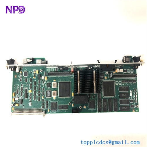
The ABB CI534V02 (Part Number: 3BSE010700R1) is a specialized communication submodule designed for integration into ABB Advant Master and S100 I/O distributed control architectures. It acts as a dedicated Modbus interface module, enabling seamless serial communication and data exchange between ABB controllers and third-party Modbus-compatible field devices, instruments, or PLCs.
- Brand: ABB (ASEA BROWN BOVERI)
- Model: CI534V02
- Part / Catalog Number: 3BSE010700R1
- Series: S100 I/O / Advant Industrial Communication Line
- Product Name: Modbus Interface Submodule / Communication Module
- Origin Country: Sweden / Germany
- Lifecycle Status: Mature / Industrial Automation Spare Part Line
- Form Factor: Standard Modular S100 Submodule Circuit Board Assembly
- Weight: Approx. 0.4 kg to 0.7 kg
- Power Rating: Standard Low-Voltage Internal Rack/Bus Power Supply
🔍 Initial Operation Checklist
- Visual and structural inspection: Inspect the printed circuit board, interface ports, and connector edge pins thoroughly for any shipping damage or physical wear.
- Confirm part identifiers: Ensure that the exact model code (CI534V02) and part number (3BSE010700R1) match your exact system rack and communication requirements.
- Check mounting alignment: Carefully align the submodule to prevent bent pins before securing it firmly into its designated S100 I/O base or communication rack slot.
- Validate power metrics: Confirm that system backplane or rack power supply inputs are stable and within nominal operating thresholds prior to energization.
- Inspect terminal connections: Ensure all serial interface wiring (such as RS-232 or RS-485 lines) is correctly terminated, shielded, and securely locked to prevent communication drops.
🛠️ Routine Maintenance & Care
- Dust and debris removal: Periodically clean accumulated dust from the circuit board surface and housing using clean, dry, oil-free compressed air.
- Terminal and connector inspection: Annually check all plug-in connectors and backplane edge pins for secure mechanical seating, thermal stress, or oxidation.
- Thermal management: Verify that control cabinet cooling fans and air ventilation paths remain unobstructed to maintain safe operating temperatures.
- Diagnostic tracking: Regularly review system event logs and diagnostic status indicators via the engineering workstation to detect early communication jitter or hardware wear.
⚠️ Troubleshooting & Common Issues
- Modbus communication timeouts: Check serial cable integrity, termination resistors, baud rate configurations, and node address (station ID) parameters if data polling fails.
- Initialization or boot errors: Reseat the submodule firmly into its base rack slot and verify that system power supply voltages are stable if it fails to initialize.
- Diagnostic fault patterns: Cross-reference front-panel LED status patterns with system error manuals to isolate protocol exceptions or hardware faults.
🛡️ Safety Precautions
- Professional personnel only: Handling, rack insertion, and system configuration must be performed strictly by certified automation and electrical engineers.
- Electrostatic discharge (ESD) protection: Always wear a properly grounded ESD wrist strap when handling bare electronic circuit boards to prevent semiconductor component damage.
- Power disconnection: Ensure control rack power supplies are completely powered down before installing or extracting communication submodules.
❓ Frequently Asked Questions (Q&A)
Q1: What is the primary function of the CI534V02 submodule?
A1: It functions as a Modbus communication interface, allowing ABB S100 I/O systems to exchange data smoothly with external Modbus RTU devices over serial links.
Q2: What serial physical layers does this interface typically support?
A2: It supports standard industrial serial communication physical standards, commonly configured for RS-232 or RS-485 connections depending on system wiring.
Q3: Can this module be hot-swapped while the control system is active?
A3: Standard industry practice for internal printed circuit boards and legacy S100 submodules requires powering down the rack to prevent electrical surges or backplane damage.