
Description
Product Introduction
⚙️ Product: DATX130
🏷️ Part Number: 3ASC25H214
🔧 Brand: ABB
🔄 Product Type: Rotor Feedback Board
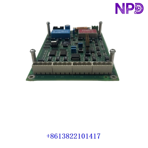
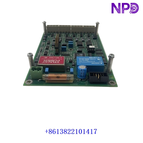
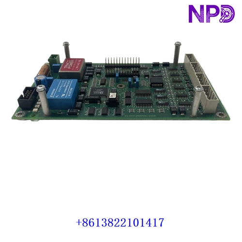
The ABB DATX130 3ASC25H214 is a rotor feedback board used in ABB drive and control equipment. Its main function is to process rotor feedback signals and provide position or speed-related feedback to the associated control system. Available ABB-related product references identify the DATX130 specifically as a Rotor Feedback Board.
⚡ The board is associated with ABB ASTAT and drive-control applications and is intended for integration into compatible ABB control equipment. It is a specialized interface board rather than a general-purpose PLC I/O module, so the exact drive model and board revision should be checked before replacement.
🔌 When replacing an existing board, compare the part number, hardware revision, connector arrangement, firmware requirements, and feedback wiring. Incorrect configuration can result in missing or unstable rotor feedback signals.
Product Datasheet
🔹 Model: DATX130
🔹 ABB Part Number: 3ASC25H214
🔹 Brand: ABB
🔹 Product Type: Rotor Feedback Board
🔹 Application: Drive Control / Rotor Feedback
🔹 Signal Resolution: 12 bit
🔹 Operating Voltage: 5 VDC
🔹 Signal Output: Analog
🔹 Temperature Coefficient: 0.01%/°C
🔹 Net Weight: Approx. 0.14 kg
🔹 Mounting: Internal Drive / Control Equipment
🔹 Country of Origin: United States or Sweden, configuration dependent
The 0.14 kg net weight and the above core technical specifications are listed in available product references for 3ASC25H214 DATX130.
Typical Applications
🔄 ABB drive control systems
⚙️ Rotor position and speed feedback
🏭 Industrial motor control
⚡ Power conversion equipment
🔧 ABB ASTAT system maintenance
📦 Industrial automation spare-parts replacement
Installation & Use
🛠️ Before installation, verify the DATX130 part number, board revision, compatible ABB drive/control system, connector arrangement, and feedback sensor wiring.
🔌 Power down the equipment before removing or installing the board. Use appropriate ESD protection and carefully inspect connectors, terminals, and the PCB for contamination or mechanical damage.
📊 After installation, verify the feedback signal, rotor position or speed indication, drive diagnostics, and control-system status. Compare the measured feedback with the expected operating value before placing the equipment back into service.
⚠️ For drive replacement work, retain the original configuration and parameter settings where applicable. Final commissioning should follow the equipment manufacturer’s approved procedure.