Description
- Model: ABB DSMB-02C (Specific Part Number: 3AFE64666606)
- Brand: ABB (Finland / Drives Division)
- Series: ACS600 / ACS800 Drive & Automation Platforms
- Core Function: Manages high-speed internal drive communication, distributed I/O allocation, and option module interfacing
- Product Type: Distributed I/O Branching / Control Board
- Key Specs: Dual DDCS Fiber Optic Channels | Power Rail Supervision | Integrated Backplane Bus Logic
- Operating Operating Voltage: Nominal 24 V DC internal logic feed (Typically derived from primary drive backplane)
- Communication Interface: DDCS (Distributed Drive Control System) proprietary optical interface protocol
- Optical Transmission Rate: 1 Mbaud to 4 Mbaud asynchronous data rate capacity
- Channel Architecture: Tri-channel branching network distributing controller data out to localized expansion racks
- Hardware Suffix Revision: Version C board layout optimized for enhanced electromagnetic compatibility (EMC)
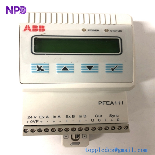
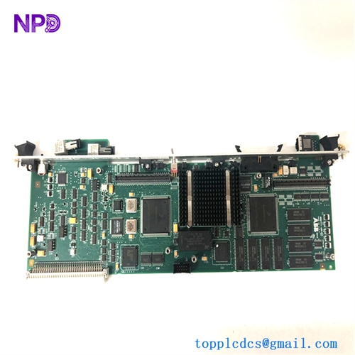
- Physical Connectors: Hardwired snap-on board connections alongside high-efficiency fiber-optic transmitter/receiver slots
- Diagnostic Subsystem: Dedicated on-board LED cluster tracking power rail health, network synchronization, and board fault vectors
- Coating Specification: Standard class G3 conformal layer defending internal traces against chemical degradation
Application Scenarios & Engineering Pitfalls
The On-Site Reality
In heavy-duty power conversion environments, your drive is only as reliable as its internal data backbone. The ABB DSMB-02C acts as a traffic controller inside specialized high-power AC or DC drive systems, bridging the main central processing board with modular peripheral I/O and fieldbus communication blocks. If this branching interface board fails, the central processor instantly loses contact with its digital or analog output channels, leading to an immediate “Drive Comms Loss” or “Auxiliary Link Fault” system shutdown. Tracking down an immediate, verified replacement for these mature components is critical to prevent entire production mills from sitting idle for weeks.
Typical Deployment Scenarios
- Heavy Metallurgy – Sectional Hot Rolling Mill Table Drives
Synchronizes multi-axis localized speed reference registers down to individual drive frames, demanding ultra-low data jitter.
- Marine Systems – Diesel-Electric Main Propulsion VFD Modules
Interfaces high-density automation feedback paths inside shipboard environments, keeping core logic isolated from electrical noise.
- Pulp & Paper – High-Torque Sectional Paper Machine Coordinated Drives
Routes real-time tension and torque profiles down to secondary drive slots to prevent sheet snap conditions during line acceleration.
- Oil & Gas – High-Horsepower Pipeline Pump Control Systems
Manages auxiliary I/O tracking (oil temperature, cooling fan feedback) and trips the system immediately if a safety parameter drops out.
Plant Survival Case Study: Steel Slitting Line Emergency Resolved
- Background: A specialty steel manufacturer was running a critical continuous sheet slitting loop driven by a large, modular ABB inverter system. The localized interface between the primary processor and the expansion I/O rack was managed via a legacy DSMB-02C control board.
- The Problem: A nearby high-power braking resistor bank suffered a thermal insulation failure, sending a severe high-frequency voltage spike through the common grounding paths. The logic-side data drivers on the active 3AFE64666606 board were knocked out, triggering a hard “Main Link Communication Error” and halting the entire line. The mill was losing over $25,000 per hour, and standard regional suppliers noted the board was long obsolete with zero active factory allocations.
- The Solution: The automation crew bypassed standard procurement channels by calling our team. We quickly pulled a clean DSMB-02C module from our legacy storage reserve, subjected it to our full multi-point fiber optic loop and validation testing, and shipped it out via an emergency overnight priority flight.
- The Result: The technician received the board at the plant by 8:00 AM the next day. The module was mounted, optical cables clicked back into place, and the drive booted up with a clean communication status profile. The slitting line resumed full operations by mid-morning, saving the plant from an extended, costly multi-week delay.
Compatible Replacement Models
When repairing legacy drive platforms, verifying board revisions and part number strings ensures your replacement slots directly into the existing software parameters.
| Original Part Number | Alternative Model | Compatibility Level | Key Differences / Structural Variances | Required On-Site Modification Steps | Cost Variance |
| DSMB-02C 3AFE64666606 | DSMB-02B (3AFE64000000) | ⚠️ Software Compatible | Version B layout. Utilizes older generation optical transceivers with a slightly different noise suppression profile. | Direct slot match, but requires careful tuning of the DDCS transmission length parameters if operating near long cable runs. | -15% |
| DSMB-02C 3AFE64666606 | 3AFE64666606 Full Core | ✅ Drop-in Replacement | Exact hardware build and revision matching. Complete compatibility with all active drive parameters. | Direct physical swap. Mount the module on its standoffs and reconnect the ribbon and optical lines. | Baseline Cost |
| DSMB-02C 3AFE64666606 | DSMB-01C | ❌ Hardware Incompatible | Alternate channel capacity configuration. Fewer fiber-optic paths and different backplane registers. | Do not attempt. The drive main controller will reject the hardware initialization sequence. | +10% |
Quality Assurance & Testing Standard Operating Procedure
To eliminate performance concerns regarding legacy inventory or warehouse-aged electronics, every single board goes through a documented, step-by-step technical evaluation before being cleared for shipment.
[Inbound Traceability Check] ➔ [Optical Microscopic Audit] ➔ [Power Rail Isolation Verification] ➔ [DDCS Fiber Optic Loop Simulation] ➔ [Anti-Static Shielded Packing] 1. Inbound Traceability & Structural Inspection
- Authentication Profiling: Verifying the physical manufacturer nameplate, internal board traces, and manufacturing revision codes against ABB’s production history.
- Chassis Assessment: Detailed optical tracking of the edge connectors, ribbon sockets, and optical housing ports to rule out structural defects.
2. Optical Microscopic Solder Joint Audit
- Joint Analysis: High-magnification optical inspection of surface solder joints, searching for cold joints, micro-fractures, or oxidation built up over extended storage.
- Fiber Port Inspection: Checking optical transmitter and receiver lenses to confirm they are completely clean and free of scratches.
3. Galvanic Power Rail Isolation Verification
- Insulation Testing: Using a specialized digital insulation tester to check the insulation barrier between the 24 V DC input trace loops and the chassis grounding plane.
- Acceptance Threshold: The insulation barrier must measure above 10 MΩ to ensure trouble-free operation inside high-noise industrial electrical rooms.
4. DDCS Fiber Optic Loop Simulation
- The Testing Environment: The DSMB-02C is mounted into a specialized testing array linked to a live ABB drive controller module.
- Data Loop Verification: We establish active DDCS communication frames across all available optical branching links, running data streams at maximum rated baud limits.
- Packet Drop Verification: Testing the link performance, tracking packet error rates using dedicated digital test diagnostics to confirm 100% signal integrity.
5. Final Quality Sign-Off and Secure Packaging
- Tagging Protocol: The testing technician signs and applies a serialized “QC Passed” sticker directly onto the anti-static packaging layer.
- ESD and Moisture Protection: The unit is wrapped in heavy anti-static bubble wrap and sealed inside a vapor-barrier bag packed with fresh desiccant.
- Shock Protection: Housed inside custom shock-absorbing foam layers within a heavy shipping box to eliminate any transportation risks.
Drive Control Board Field Troubleshooting Quick Reference
❗ SAFETY FIRST: Disconnect and lock out all main incoming power lines feeding the drive system before opening cabinet doors or servicing internal boards. Verify that all internal DC bus capacitors have completely discharged down to 0 V using a verified, high-voltage voltmeter.
Q: The drive main controller throws an immediate “DDCS Channel Error” or “Branch Communication Loss” right at power-up.
A: Correlation: High. This typically points to a failure of the line-driving circuits or a damaged optical component on the DSMB-02C card.
- Safely isolate the power feed line.
- Carefully inspect the fiber optic cables running into the board ports. Look for sharp bends or internal cracking in the plastic core lines.
- Unplug the optical connectors while the system is powered and verify that you see a steady red light emitting from the transmitter port. If the transmitter lens is dark while the board has power, the board’s internal logic has failed. Replace the board.
Q: The drive functions perfectly at idle speed, but as soon as the motor draws full running current, the distributed I/O links randomly drop out, causing a system trip.
A: Correlation: High. This pattern indicates that the noise suppression or grounding filters on the DSMB-02C module have degraded over time. When high switching currents flow through the nearby power components, electrical noise slips past the degraded filters, corrupting your internal data streams.
- Check that the board’s mounting screws are torqued down completely against the grounded cabinet backplate.
- Check for any signs of heat discoloration on the small surface-mount filter blocks next to the ribbon connectors. If the grounding contacts are clean but the faults continue during high-current operations, swap out the board for a verified spare.
Q: The main power rail LEDs on the board face stay completely dead when the panel breaker is engaged, but the drive’s main display unit boots normally.
A: Correlation: Medium-High. The internal input protection fuse or the voltage tracking components on the DSMB-02C card have blown due to a localized line spike on the internal 24 V DC supply line.
- Use a digital multimeter to measure the incoming voltage right at the power input terminals or backplane ribbon lines feeding the card.
- If power is present but the board show no signs of life, the board’s internal power path is damaged. Replace the entire card assembly.
❗ Critical Installation Guidelines for On-Site Technicians
- Handle Optical Fibers with Extreme Care: Never bend fiber optic cables past their minimum bend radius (typically 25 mm). Sharp bends will cause internal light attenuation, leading to intermittent data dropouts that are incredibly frustrating to isolate during drive commissioning. Always clean the cable tips before plugging them back into the transceiver ports.
- Verify Ribbon Cable Alignment: Ensure that the main internal multi-pin ribbon cables are pushed fully into their sockets and locked down securely. A slightly crooked ribbon connection can result in intermittent input faults or unexpected component responses during runtime.
- Ensure Clean Grounding Planes: When mounting the new board onto its standoffs, ensure that the contact surfaces are completely clean of dust or oxidation. The board relies on these physical mounting points to ground out electromagnetic interference (EMI) generated by the drive’s high-speed switching transistors.