
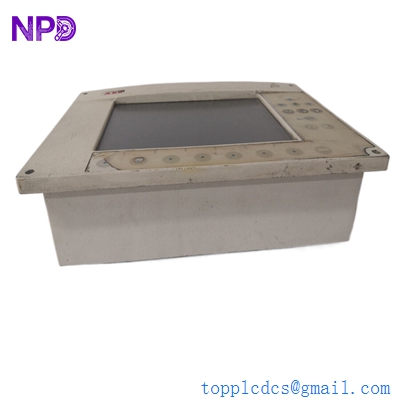
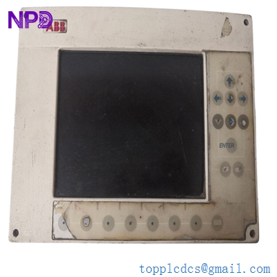

Description
- Model: ABB GOP2 (Often associated with the 87TS01-E or 87TS02 base)
- Brand: ABB (Switzerland/Germany)
- Series: Procontrol P13 (Advanced Power Plant Automation)
- Core Function: Central Processing and Communication Unit for the P13 bus system
- Product Type: Central Controller / Processor Module
- Key Specs: Multi-protocol support, high-speed backplane integration, 24V DC logic
- Architecture: 32-bit high-speed processor for real-time control
- Backplane Interface: Parallel P13 bus connection (high-density DIN connector)
- Communication: Supports AF 100 (Advant Fieldbus) or specialized serial links depending on the daughterboard
- Diagnostics: Comprehensive self-monitoring with front-panel “Run,” “Error,” and “Status” LEDs
- Memory: On-board Flash/EPROM for application logic and RAM for dynamic data
- Configuration: Set via P13 engineering software (Progress / Control IT)
- Cooling: Passive convection; requires standard rack airflow management
- EMC Rating: Industrial-grade shielding for high-interference power plant environments
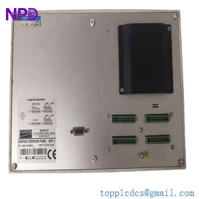
ABB GOP2
Installation & Configuration Guide
Phase 1: Pre-Installation (Estimated time: 20 minutes) ⚠️ Safety First:
- The GOP2 is the Heart of the P13 rack. Replacing it requires a complete system shutdown of that specific control branch.
- Project Backup: Ensure you have the latest
.p13or.binconfiguration files. The GOP2 acts as the traffic controller for all I/O modules in the rack. - Check the revision. GOP2 modules often have daughterboards (like a 87TS01) attached. Ensure the assembly matches your existing hardware exactly.
Phase 2: Removal (Estimated time: 10 minutes)
- Label Front Cables: If there are serial or fiber optic cables connected to the front of the module, label them (TX/RX) clearly.
- Release Retainers: Loosen the top and bottom screws on the faceplate.
- Extraction: Use the pull-handles to withdraw the module from the backplane. Be careful not to tilt the module, as the P13 backplane pins are long and easily bent.
- Inspect Slot: Ensure no carbon buildup or dust is present in the female connectors of the rack.
Phase 3: Installation (Estimated time: 15 minutes)
- Address Settings: Match the DIP switches or rotary dials on the GOP2’s PCB to the original unit. This defines the module’s address on the P13 bus.
- Slide and Seat: Align the module with the card guides and push firmly until you feel the backplane engage.
- Secure: Tighten the screws to ensure the module is grounded and cannot vibrate loose.
Phase 4: Commissioning & Sync (Estimated time: 45 minutes)
- Apply 24V control power to the rack.
- Initial Boot: The “Power” LED should be green. The “Error” LED may flash until the application is synchronized.
- Software Link: Connect your engineering PC. Perform a “Node Scan” to ensure the GOP2 is visible.
- Download Logic: Upload the site-specific project. Once complete, switch the module to “Run” mode and verify that the “Status” LED confirms active communication.
Customer Cases & Industry Applications
Case 1: Hydroelectric Power Plant Synchronization A hydro plant in Norway experienced a total loss of communication between its I/O racks and the central SCADA. The failure was traced to a GOP2 controller that had suffered a processor fault due to a cooling fan failure in the cabinet. We delivered a New Surplus GOP2 in 4 days. After swapping the module and reloading the configuration, the plant restored its remote monitoring and control capabilities without a costly trip to the site by OEM engineers.
Case 2: Industrial Steam Turbine Maintenance A large paper mill utilized the Procontrol P13 series for its combined heat and power (CHP) plant. During a scheduled outage, the GOP2 was found to have intermittent memory errors. Since the P13 is a legacy system, lead times for new parts were excessive. By utilizing our New Surplus GOP2 stock, the mill was able to replace the aging hardware and resume production on schedule, ensuring the stability of their turbine control logic for another decade.
Frequently Asked Questions (FAQ)
Q: Can the GOP2 replace a GOP1 module? A: To be honest, it depends on your software version and backplane. The GOP2 is a more advanced version with higher processing capacity, but it may require a firmware update in the surrounding I/O modules to function correctly as a direct replacement.
Q: Does the GOP2 include the 87TS01-E communication board? A: Most of our GOP2 stock comes as a complete assembly with the standard daughterboards included. However, please verify the specific sub-part numbers (e.g., 3BHE…) on your order to ensure a 100% match.
Q: Why is the “Error” LED on after I installed the new module? A: This usually indicates an address conflict or a blank memory. If you haven’t downloaded the project logic yet, the “Error” LED is a standard warning. If it persists after a download, double-check your DIP switch settings against the original module.
Q: How do I know the “New Surplus” capacitors are still good? A: We perform a 24-hour “burn-in” and power-up test on all Procontrol modules. Because these units were stored in a climate-controlled, non-energized environment, the electrolytic capacitors are in far better condition than a “refurbished” unit that has been running in a hot cabinet for 10 years.
Q: Is “Hot-Swapping” the GOP2 allowed? A: Absolutely not. The GOP2 is the bus master. Pulling it while the rack is powered can cause unpredictable signals to be sent to your field devices (valves, breakers, etc.) and may damage the backplane electronics.
I’m always open to corrections if I get something wrong; the best way to handle that is to just tell me what I missed or what I need to know! You can also always turn off the use of this personal context in your settings.


