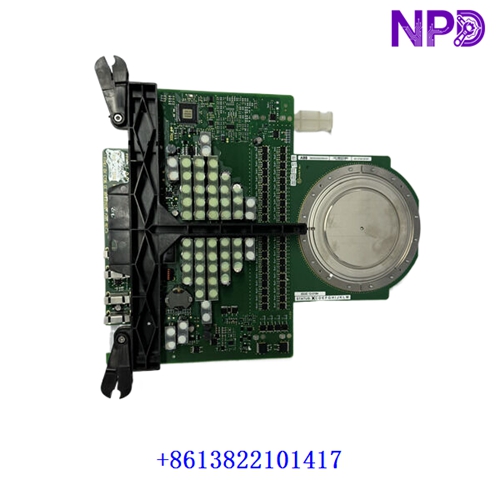

Description
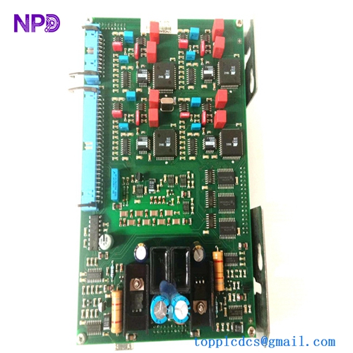
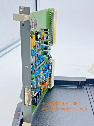
This technical datasheet provides comprehensive specifications, installation procedures, routine maintenance guidelines, troubleshooting steps, safety precautions, and frequently asked questions for the ABB HIEE300690R0001 AR C093 AE01 circuit interface module. Engineered for industrial automation and electrical control systems, this high-performance component ensures precise signal transmission and robust system integration.
⚙ Product Technical Parameters
- 1. Brand: ABB
- 2. Model: HIEE300690R0001 / AR C093 AE01
- 3. Series: Industrial Automation Control Series
- 4. Product Name: Circuit Interface Module
- 5. Country of Origin: Switzerland
- 6. Physical State: Solid-state electronic hardware module
- 7. Dimensions: 350 mm × 120 mm × 50 mm (Standard rack modular format)
- 8. Weight: 0.9 kg (Gross weight approx. 1.0 kg)
- 9. Origin Location: Baden, Switzerland
- 10. Power Consumption: Standard internal rail power draw under 12W

📋 Initial Operation Checklist
Before powering on the system for the first time, verify all physical and electrical configurations to prevent equipment damage or interface faults:
- Inspect the module housing, edge connectors, and terminal pins for any signs of transit damage or environmental contamination.
- Confirm that the input control voltage supply matches the nominal rating specifications with appropriate system grounding.
- Verify that all backplane connections and interface wiring harnesses are securely seated and locked.
- Ensure ambient operating temperature falls within the specified industrial environmental limits.
- Check diagnostic indicator LED definitions in the system manual to prepare for status interpretation during startup.
🛠 Routine Maintenance and Upkeep
Regular maintenance ensures optimal operational longevity and sustained signal reliability across automated control networks:
- Perform bi-annual visual inspections to detect dust accumulation or corrosion on terminal blocks and connectors.
- Clean module exterior surfaces using a dry, anti-static microfiber cloth; avoid liquid solvents or aerosol cleaners.
- Monitor module status indicators periodically and schedule planned diagnostic checks during facility maintenance windows.
- Verify terminal screw torque values annually to prevent intermittent contact resistance due to industrial vibration.
🔧 Troubleshooting and Common Issues
Systematic problem isolation minimizes downtime when operational anomalies arise in the field:
- Status LED Unlit: Check external circuit breakers, verify internal power supply rails, and inspect input fuse continuity.
- Interface Signal Failure: Inspect field wiring, check terminal block seating, and confirm channel configuration settings in the controller software.
- Intermittent Data Glitches: Check for electromagnetic interference (EMI) sources near signal routing and ensure proper shielding and cabinet grounding.
- Module Overheating: Ensure adequate enclosure ventilation clearance and verify that surrounding cabinet cooling fans are fully operational.
🛡 Safety Precautions
Strict adherence to safety guidelines protects personnel from electrical hazards and prevents permanent hardware damage:
- Always disconnect main power supplies before installing, removing, or servicing the module.
- Observe standard electrostatic discharge (ESD) wrist strap protocols when handling electronic printed circuit boards.
- Do not operate the device in explosive or hazardous atmospheres unless certified for specific zone deployment.
- Ensure all field wiring complies with local electrical safety codes and manufacturer recommendations.
❓ Frequently Asked Questions (Q&A)
- Q1: Can this interface module be hot-swapped during active system operation?
- A1: Hot-swapping is not recommended unless explicitly supported by the specific backplane rack architecture and system power management configuration. Always power down the rack slot before insertion or removal.
- Q2: What should I do if a communication or signal fault LED blinks continuously?
- A2: A flashing status light typically indicates a hardware self-test fault or interface mismatch. Cycle power to the unit; if the error persists, check diagnostic error registers via the control software or consult technical support.
- Q3: Is custom programming required prior to putting the module into service?
- A3: The hardware functions as a standard circuit interface module, but channel allocation and mapping configurations must be defined within the primary controller software environment.