Description
- Model: ABB IOR810
- Brand: ABB (Bailey Controls)
- Series: Symphony Harmony / INFI 90 / Symphony Plus
- Part Number: P-HB-IOR-80010000
- Core Function: Opto-isolated interposing relay output for field device control
- Product Type: Relay Output Termination Unit
- Key Specs: 16 Isolated Channels 24 V DC / 125 V DC / 120 V AC Contact Ratings
- Channel Density: 16 independent relay output channels
- Input Logic: 24 V DC from the controller (via ribbon cable/backplane)
- Contact Types: Form A (Normally Open) or Form C (Changeover), configuration dependent
- Isolation: High-voltage opto-isolation between logic side and field side
- Contact Ratings:
- 5 A at 120 V AC
- 5 A at 24 V DC
- 0.5 A at 125 V DC (inductive)
- Mounting: Standard Symphony Harmony / INFI 90 baseplate or DIN rail
- Indicators: Individual per-channel status LEDs
- Terminal Type: Screw-terminal compression blocks
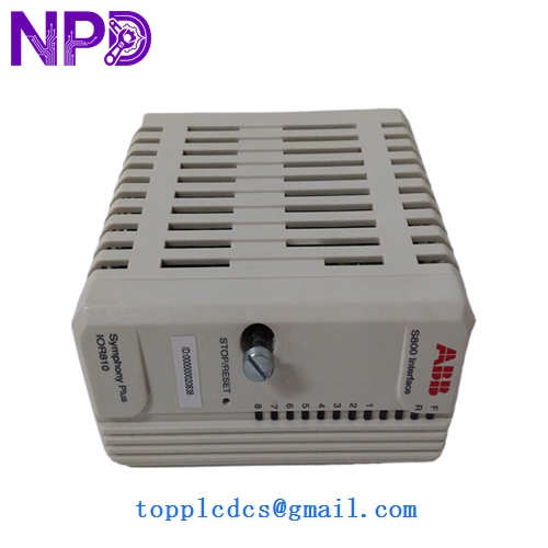
ABB IOR810 P-HB-IOR-80010000
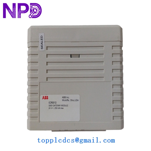
ABB IOR810 P-HB-IOR-80010000
ABB IOR810 P-HB-IOR-80010000
Application Scenarios & Pain Points
In the ABB Bailey Symphony/INFI 90 ecosystem, the IOR810 serves as the heavy-duty muscle for the digital output modules. While the controller manages the logic, it isn’t designed to directly switch high-current solenoids or motor starters. The IOR810 bridges this gap, providing the necessary isolation to protect the expensive control hardware from field-side electrical noise and surges. If this module fails, your commands might “fire” in the software, but the physical valves or pumps won’t budge.
Typical Application Scenarios:
- Power Plant Steam Cycle Controlling high-pressure steam valves and motorized actuators where 125 V DC switching is common.
- Boiler Feed Pump Control Interfacing the DCS logic with the high-voltage motor starters.
- Emergency Trip Systems Acting as the final physical relay to drop power to safety-critical solenoids.
- Water Treatment Plant SCADA Managing chemical dosing pumps and large-scale aeration blowers.
Case Study: The “Welded Contact” Crisis
Background: A coal-fired plant in the Ohio River Valley was experiencing a “Valve Fail to Close” alarm. The DCS logs showed the command was de-energized, but the valve remained open.
Problem: We traced the circuit back to the IOR810 (P-HB-IOR-80010000). Upon opening the module, we found that one of the relays had its contacts welded shut. This was caused by an inductive kickback from a failing solenoid valve that lacked a proper surge suppressor (flyback diode).
Solution: We replaced the IOR810 module and added an external snubber to the field wiring to prevent a repeat failure.
Result: – Safety Restored: The valve now operates correctly and provides positive shut-off.
- Downtime Minimized: Swapping the IOR810 took less than 10 minutes once the spare arrived.
- Engineer’s Insight: “If you are switching DC loads with the IOR810, always use a diode across the load. Without it, the arcing will eventually weld these relays, and your ‘Safe State’ will be anything but safe.”
Compatible Replacement Models
The IOR810 has been a standard for decades, but there are variations in the P-HB part numbers.
| Original Model | Replacement Model | Compatibility | Note |
|---|---|---|---|
| IOR810 | P-HB-IOR-80010000 | ✅ Exact Match | The standard 16-channel relay module. |
| IOR810 | IOR800 | ⚠️ Software | Older version; check contact ratings and pinouts. |
| IOR810 | Digital Output Card | ❌ Incompatible | This is a termination unit, not a controller card. |
Troubleshooting Quick Reference
| Symptom | Possible Cause | Relation | Quick Check | Action |
|---|---|---|---|---|
| LED is ON, but no field action | Blown Fuse / Welded Relay | ✅ High | Check continuity across the relay contacts. | Replace module or the individual relay. |
| No LED and no action | Ribbon Cable Failure | ⚠️ Med | Inspect the cable from the DO module to the IOR810. | Reseat or replace the ribbon cable. |
| Multiple channels failed | 24V Logic Power Loss | ✅ High | Measure 24V DC at the module power terminals. | Check the cabinet power supply/fuses. |
| Intermittent “Chattering” | Low Logic Voltage | ⚠️ Med | Measure voltage at the coil side of the relay. | Check for voltage drop in the logic wiring. |
❗ Pro Tip: Relay Replacement
The IOR810 uses plug-in style relays in some revisions. Before throwing the whole board away, see if the relay itself is socketed. If it is, you can often buy just the relay (usually a standard Omron or similar industrial brand). However, if the traces on the board are burnt from a high-voltage surge, the entire P-HB-IOR-80010000 must be replaced to ensure isolation integrity.
Wiring & Mounting:
The IOR810 is designed for high-density cabinets.
- Label your wires! 16 channels mean 32 to 48 wires depending on whether you use NO, NC, or CO contacts.
- Ensure the DIN rail mounting is secure; loose modules can lead to vibration-induced failures in the ribbon cable connectors.
- If you’re switching 120 V AC, ensure your cable routing keeps the high-voltage field wires separate from the low-voltage logic ribbon cables to avoid EMI interference.