
Description
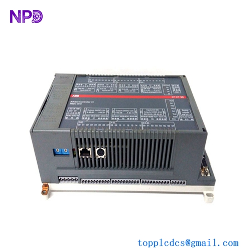
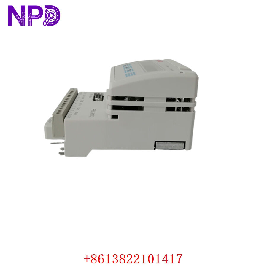
- Model: ABB PFEA112-20 (Specific Part Number: 3BSE050091R20)
- Brand: ABB (Sweden / Force Measurement Division)
- Series: PFEA Tension Electronics Family (Advanced IP65 Version)
- Core Function: Processes millivolt signals from Pressductor load cells into high-accuracy analog/digital web tension values
- Product Type: Tension Electronics Unit / Load Cell Amplifier
- Key Specs: 24 VDC Power Input | Combined Load Cell Inputs (Up to 2) | Profibus-DP Fieldbus Interface | IP65 Rugged Enclosure
- Operating Input Power: 24 V DC (18 to 36 V DC continuous range, 15 W maximum power consumption)
- Load Cell Compatibility: Connects up to 2 ABB Pressductor pillow block or radial load cells (e.g., PFTL101, PFCL201 series)
- Excitation Output Stage: Integrated 2.0 A AC, 400 Hz high-frequency drive circuit matching Pressductor requirements
- Fieldbus Communication Interface: 1x built-in Profibus-DP port supporting up to 12 Mbit/s data transmission speeds
- Analog Output Signal Mapping: 2x programmable 4 to 20 mA or 0 to 10 VDC outputs tracking total, left, or right side web tension
- Discrete Digital Relay Ports: 4x programmable solid-state digital outputs for tension threshold limits or system alarms
- Display Interface Block: Multi-line backlit alphanumeric display paired with a 4-button front programming keypad
- Physical Enclosure Protection: IP65 (NEMA 4X equivalent) dust and moisture proof wall-mount structural framework
- Signal Resolution Precision: 16-Bit A/D conversion logic with an internal processing update cycle of 1 ms
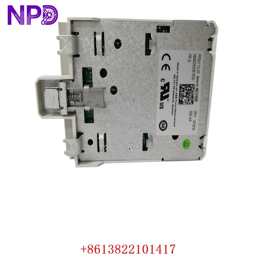
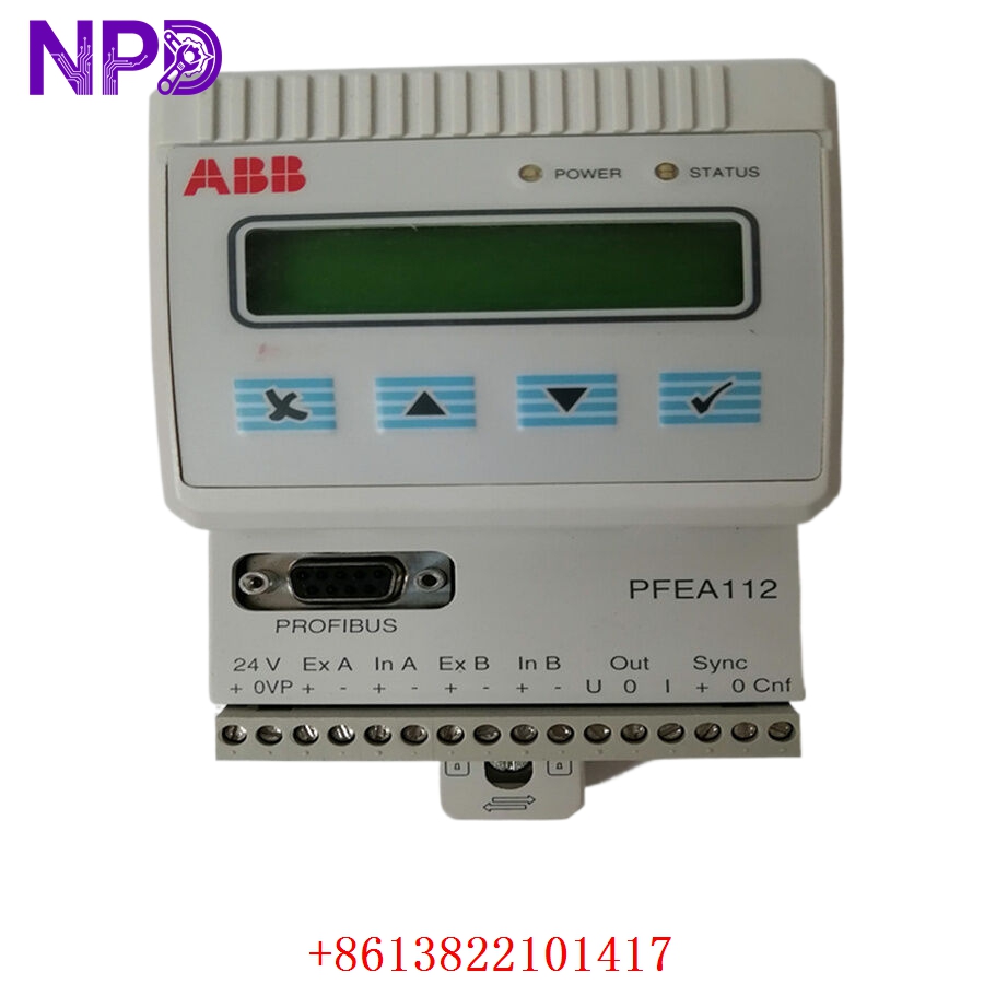
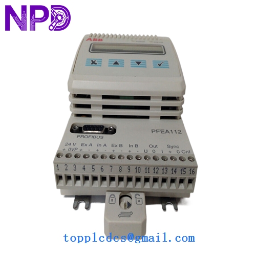
ABB PFEA112-20 3BSE050091R20
Application Scenarios & Engineering Pitfalls
The On-Site Reality
In continuous conversion lines processing raw paper webs, aluminum foil, or flexible laminates, stability is everything. The ABB PFEA112-20 serves as the precise data hub for your force tracking loop. It handles the raw electrical signals from your load cells, amplifies them, and sends real-time tension values back to your primary PLC or drive cabinet. If this controller fails or loses its fieldbus connection, your closed-loop tension system loses its feedback mechanism, leading to web tracking deviations, wrinkling, or sudden product breaks. Having a pre-tested, verified replacement ready for immediate installation avoids letting your production lines sit dark for days.
Typical Deployment Scenarios
- Pulp & Paper – High-Speed Rewinders and On-Line Coating Stations
Processes real-time force data across dual-ended rollers, calculating combined total sheet tension vectors at production speeds.
- Metal Converting – Aluminum Foil and Thin-Gauge Steel Slitting Lines
Maintains high-accuracy tension tracking under high-speed mechanical shifts, preventing material distortion.
- Flexible Packaging – Multi-Station Rotogravure Printing Presses
Feeds real-time tension data into section drives over Profibus networks to ensure perfect print registration across multiple colors.
- Rubber & Tire Production – Calendering Machine Fabric Control Loops
Monitors heavy-duty 20 kN+ load cell signals inside high-temperature, high-vibration manufacturing bays.
Plant Survival Case Study: Packaging Line Recovery
- Background: A large-scale film extrusion and laminating plant was running a continuous, multi-layer high-speed line. The web tension control loop relied on a wall-mounted PFEA112-20 controller hooked up to a Siemens S7-400 safety PLC via a Profibus-DP connection.
- The Problem: During an unexpected condensation drip incident in the auxiliary ceiling space, water seeped through a loose cable gland on top of the controller housing. The internal power converter tracking traces shorted out, blowing the board and severing the Profibus communication link. The primary extrusion line dropped its line interlocks and tripped, halting production. The plant faced downtime losses estimated at $22,000 per shift, and local component distributors could not guarantee an immediate replacement for that specific Profibus configuration model.
- The Solution: The plant’s technical leader bypassed standard procurement backlogs by contacting our support team directly. We pulled an original, unused surplus 3BSE050091R20 unit from our clean inventory core, ran it through our comprehensive multi-channel signal injection validation and Profibus node communication testing, and shipped it out via overnight express.
- The Result: The unit was delivered to the mill gate by 7:30 AM the following morning. The maintenance team mounted the IP65 enclosure, matched the hardware Profibus address node switches to the old setup, and uploaded the original calibration constants using the keypad interface. The extrusion line resumed full operations before noon, saving the facility from a prolonged, costly multi-week delay.
Compatible Replacement Models
When maintaining high-precision force amplification systems, paying close attention to model suffix numbers (e.g., -0, -10, -20) ensures your replacement matches your required fieldbus communication needs.
| Original Part Number | Alternative Model | Compatibility Level | Key Differences / Structural Variances | Required On-Site Modification Steps | Cost Variance |
| PFEA112-20 3BSE050091R20 | PFEA112-0 (3BSE030369R1) | ❌ Hardware Incompatible | Baseline version without any built-in fieldbus communication blocks. Features standard analog outputs only. | Do not substitute if using fieldbus connectivity. The lack of a Profibus port will trigger a permanent communication error at the main PLC. | -30% |
| PFEA112-20 3BSE050091R20 | PFEA112-20 Full Suffix Parity | ✅ Drop-in Replacement | Exact hardware build, revision, and casing match. Complete compatibility with all active load cell installations. | Direct physical swap. Transfer your wiring terminal strips, set the Profibus node address switch, and run the tare calibration. | Baseline Cost |
| PFEA112-20 3BSE050091R20 | PFEA111-20 (3BSE050090R20) | ⚠️ Software Compatible | Simplified single-channel input configuration framework instead of the dual-channel input support found on the 112 series. | Can be used only if your current setup uses a single load cell input point. Requires reviewing the system’s force summation parameters. | -15% |
Quality Assurance & Testing Standard Operating Procedure
To address the high-reliability demands of safety-critical manufacturing lines, every single ABB tension amplifier undergoes a documented, multi-point functional verification process before being packaged and cleared for site shipment.
[Inbound Serialization Log] ➔ [Optical Gland/Seal Integrity Check] ➔ [Power Isolation & Dielectric Test] ➔ [Dual-Channel Force Loop Simulation] ➔ [Profibus Node Communication Validation] 1. Inbound Serialization & Visual Evaluation
- Authenticity Profiling: Verifying the physical manufacturer nameplate, internal board traces, and firmware version structures against ABB’s Force Measurement Division production history.
- Enclosure Assessment: Detailed checking of the IP65 rubber sealing rings, cable entry paths, and front-panel keyboard membrane to ensure complete weather protection.
2. Microscopic Solder Joint & Power Isolation Testing
- Joint Analysis: High-magnification optical inspection of surface solder joints, searching for cold joints, micro-fractures, or oxidation built up over extended storage.
- Dielectric Isolation Testing: Applying a 500 V DC test barrier between the 24 V DC power input rails, analog outputs, and the main grounding frame using a Fluke 1507 insulation tester.
- Pass Threshold: Isolations must measure above 10 MΩ to ensure trouble-free operation inside high-noise industrial environments.
3. Dual-Channel Force Loop Simulation
- The Testing Environment: The PFEA112-20 unit is mounted onto our specialized technical diagnostic bench and hooked up to an adjustable millivolt input generator loop mimicking two independent Pressductor load cells.
- Dynamic Signal Output Tracking: We inject exact force simulation steps (0 mV, 10 mV, 20 mV, and 40 mV) across both channels, verifying that the display values and the 4 to 20 mA analog output loops track linearly without signal drift or hysteresis.
4. Profibus-DP Fieldbus Node Validation
- The Configuration Loop: The module’s communication port is integrated into an active Profibus testing network driven by a Master PLC node configuration.
- Cyclic Data Verification: We test different network speeds (up to 12 Mbit/s) to ensure the controller passes tension tracking bytes and system status flags without packet loss or interface lag.
5. Final Quality Sign-Off and Secure ESD Packaging
- Tagging Protocol: The testing technician signs and applies a serialized “QC Passed” sticker directly onto the anti-static packaging layer.
- ESD and Moisture Protection: The unit is wrapped in heavy anti-static bubble wrap and sealed inside a vapor-barrier bag packed with fresh desiccant.
- Shock Protection: Housed inside custom shock-absorbing foam layers within a heavy shipping box to eliminate any transportation risks.
Tension Controller Field Troubleshooting Quick Reference
❗ SAFETY FIRST: Disconnect and lock out all primary power lines feeding the controller panel before loosening terminal connections or performing cable continuity checks. Ensure your field instrument shielding is completely isolated from high-current power cables to prevent electrical noise corruption.
Q: The controller display is active, but the Master PLC logs a persistent “Profibus Communication Failure” or “Node Offline” fault flag.
A: Correlation: High. This problem is usually caused by an incorrect hardware address setting, a loose network connector plug, or a failure of the internal Profibus interface chip on the PFEA112-20 board.
- Check the two rotary hexadecimal or DIP switch arrays located on the main board inside the housing. Verify that the node address matches the exact hardware identifier configuration specified in your PLC’s GSD hardware layout.
- Inspect the sub-D Profibus connector plug. Ensure the inline termination resistor switch is flipped to the “ON” position if this controller sits at the physical end of the network run cable segment.
- If the wiring is correct and the node settings match but communication cannot be established, the internal communication transceiver block has failed. Replace the controller module.
Q: The tension values on the screen fluctuate wildly when the guide roller spins, though the physical material web looks stable and taut.
A: Correlation: Medium-High. This behavior usually indicates an ungrounded cable shield, or worn-out bearings on the measuring roller generating structural harmonics that confuse the controller.
- Use a digital multimeter to verify that the load cell signal cable shield is terminated to ground at the PFEA112-20 enclosure terminal block only. Grounding both ends of the shield creates a ground loop that injects electrical noise into your signal line.
- Check the raw millivolt inputs from your load cells while the machine runs empty. If you see high-frequency voltage spikes, inspect the guide roller bearings for mechanical imbalance or physical wear. If the roller is mechanically balanced, the controller’s internal filtering frequency parameters may need adjustment to smooth out the signal.
Q: The display shows a hard “Excitation Overcurrent Fault” code, and the analog output signal locks at a flatline minimum value.
A: Correlation: High. This warning means the controller’s internal 400 Hz power driver circuit is overloaded, typically due to a short circuit in the field wiring or a failed coil inside one of the attached load cells.
- Shut down the controller power. Disconnect the excitation wires running to your load cells from the terminal strip inside the housing.
- Power the controller back up. If the overcurrent fault code clears, the problem lies out in the field. Use an LCR meter to check the loop resistance of your field cabling and load cell coils to locate the short circuit down to ground. If the fault remains active with the field wires removed, the controller’s internal power supply stage is damaged. Swap out the unit.
❗ Critical Installation Guidelines for On-Site Technicians
- Match Hardware Addresses Exactly: Never swap a Profibus-enabled controller without verifying its address node switches. The PFEA112-20 reads its network node ID directly from physical hardware switches inside the enclosure. If you mount a replacement unit without matching these switches to the old card’s configuration, your primary PLC will fail to recognize the device on the network.
- Verify Cable Gland Sealing Protection: When terminating your field wiring connections inside the IP65 enclosure housing, ensure every single cable gland is turned down tight around the outer wire insulation sheets. Point cable entries downward to prevent moisture from traveling down the wires and into the internal board tracks.
- Execute an On-Site Tare Calibration: After replacing the controller unit, you must perform a fresh “Zero Tare” routine with the machine empty before threading any material through the rollers. This step accounts for the physical weight of your guide roller assembly, ensuring your system registers accurate, linear web tension metrics during production.