Description
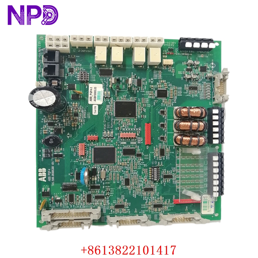
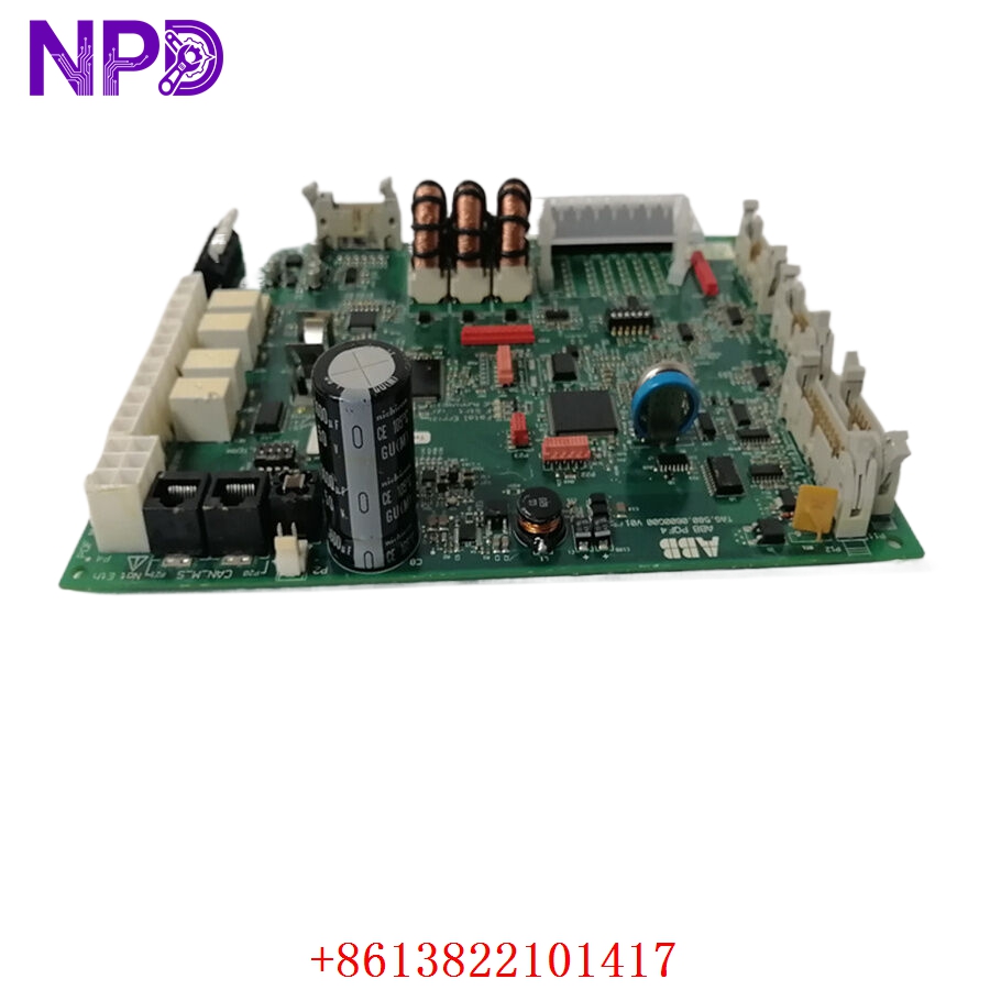
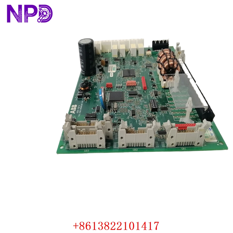
- Model: ABB PQF4-3 TAS.580.0600G00 V01
- Brand: ABB
- Series: PQF Reactive Power Compensation Series
- Core Function: Automatic power factor correction and capacitor bank control
- Product Type: Power Factor Controller / Reactive Power Compensation Controller
- Key Specs: 380 V AC system 8 relay outputs RS485 Modbus RTU
- Rated System Voltage: 380 V AC three-phase
- Auxiliary Supply Voltage: 220 V AC ±15%
- Power Factor Measurement Range: 0.2–1.0
- Control Accuracy: ±0.02 power factor
- Compensation Capacity: Up to 600 kvar
- Relay Output Channels: 8 capacitor control outputs
- Communication Interface: RS485
- Communication Protocol: Modbus RTU
- Frequency Adaptation: 50/60 Hz auto-detection
- Power Consumption: ≤10 W
- Installation Method: DIN rail or panel mounting
- Operating Temperature: -10 °C to +55 °C
- Dimensions: Approximately 144 × 144 × 120 mm
- Weight: Approximately 0.8 kg
Application Scenarios & Engineering Pain Points
Power factor controllers are one of those devices people only notice after the electricity bill becomes painful… or when capacitor banks start exploding unexpectedly.
In older industrial plants, especially sites packed with motors, welding equipment, VFDs, compressors, and induction furnaces, reactive power becomes a silent problem. Utilities penalize low power factor, transformers run hotter, and cable losses increase. Operators usually blame the electrical infrastructure, but the real issue often sits inside the compensation cabinet.
That’s where the PQF4-3 controller comes in.
The module continuously measures the system power factor and automatically switches capacitor banks in and out to maintain stable compensation. In practice, it acts like the traffic controller of the low-voltage compensation system.
Typical application scenarios:
- Automotive Manufacturing – Welding Robot Power Systems
Rapid motor and welding load changes require fast capacitor bank switching to stabilize PF during production peaks. - Steel & Metallurgy Plants – High Reactive Load Environments
Handles heavy inductive loads from rolling mills, pumps, and furnace auxiliaries. - Water Treatment Facilities – Pumping Stations
Improves transformer efficiency and reduces utility penalties caused by large motor groups. - Commercial Complexes – Central HVAC Compensation
Controls capacitor banks supporting chillers and air handling systems with fluctuating demand. - Mining & Cement Plants – Harsh Electrical Environments
Used where high harmonic content and repeated motor starts stress compensation equipment.
Real Integration Example – “The Utility Penalty Nobody Understood”
A packaging plant upgraded several production lines with new VFD-driven motors. Production improved, but the monthly electricity bill suddenly increased by almost 18%.
Operations blamed the utility company.
Finance blamed production.
Maintenance blamed the transformers.
The real issue?
Power factor collapsed during peak load periods because the existing compensation controller reacted too slowly and several capacitor stages stopped switching correctly.
We installed a replacement PQF4-3 TAS.580.0600G00 V01 controller and rebalanced the capacitor stages.
Results after commissioning:
- Power factor stabilized around 0.96
- Utility reactive power penalties disappeared
- Transformer temperature dropped several degrees during peak shifts
- Capacitor switching became balanced again
Interesting part? The old controller still “looked operational.” LEDs were active. Display worked. But two relay outputs had degraded contacts causing intermittent stage failure.
That’s the kind of problem that wastes weeks during troubleshooting.
Compatible Replacement Models
✅ Direct Replacement (Recommended)
- ABB PQF4-3 TAS.580.0600G00 V01
- Same compensation logic
- Same relay output arrangement
- Same Modbus RTU communication structure
- No major cabinet rewiring required
- ABB PQF6-3 TAS.580.0800G00 V01
- Expanded compensation capacity
- Similar programming structure
- Suitable when additional capacitor stages are planned
- Verify panel dimensions before installation
⚠️ Software / Engineering Review Required
- ABB RVC Series Controllers
- Improved harmonic analysis capability
- Different menu structure and parameter mapping
- Requires commissioning parameter migration
- CT ratio and switching logic must be reconfigured
- Third-Party Modbus PF Controllers
- Modbus communication may work
- Relay timing logic often differs
- Existing capacitor sequencing may require tuning
❌ Hardware Modification Required
- Generic PLC-Based Compensation Logic
- Requires complete custom programming
- Additional relay cards needed
- No built-in PF compensation algorithm
- Longer commissioning and troubleshooting time
From a system integration perspective, sticking with the same ABB compensation family usually saves time during shutdown windows. Rebuilding capacitor logic under pressure is not fun… especially when the plant wants power restored immediately.
Troubleshooting Quick Reference
| Fault Symptom | Possible Cause | PQF4-3 Relevance | Quick Check Method | Recommended Action |
|---|---|---|---|---|
| Power factor remains low | Capacitor stage failure | ⚠️ Medium | Check relay output LEDs and capacitor contactors | Inspect capacitor bank |
| Controller display active but no switching | Relay contact degradation | ✅ High | Measure relay output switching voltage | Replace controller |
| Capacitors switching rapidly | Incorrect CT polarity | ⚠️ Medium | Verify CT direction arrow | Reverse CT wiring |
| Overcompensation alarms | Incorrect PF setpoint | ⚠️ Medium | Review target PF parameter | Adjust settings |
| Modbus communication timeout | RS485 wiring issue | ⚠️ Medium | Measure A/B polarity and termination | Check shield grounding |
| Controller completely dead | Auxiliary supply loss | ❌ Low | Measure 220 V AC supply | Check fuse and breaker |
| Capacitor bank imbalance | Output stage mismatch | ✅ High | Verify relay sequence operation | Reconfigure outputs |
| Harmonic overheating | Excessive THD in network | ❌ Low | Measure harmonics with analyzer | Add detuned reactors |
Common Engineering Pitfalls
❗ CT polarity mistakes are by far the most common problem.
I’ve seen perfectly healthy controllers installed backward so the system actually made power factor worse instead of better.
Classic symptoms:
- Capacitors switching continuously
- PF oscillating between lagging and leading
- Transformer humming loudly
- Utility penalties getting worse after “repair”