
Description
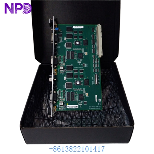
- Model: ABB QHFD 410 (QHFD410)
- Brand: ABB
- Series: Turbine Governor & Heavy Power Control Series
- Core Function: Delivers regulated multi-rail auxiliary power, signal amplification, and actuator driver outputs for turbine speed governor systems
- Product Type: Governor Power Supply & Actuator Driver Unit
- Key Specs: Multi-voltage inputs (135 V, ±12 V DC, ±15 V DC, 24 V AC, 24 V DC), local power amplifier, 0–110% output range, lightweight (850 g) chassis
- Supply Status: ⚠️ Obsolete / Limited Factory Stock & Verified Surplus Available
- Stock: Ready Stock (Subject to prior sale)
- Warranty: 12 Months (From shipment date)
- Ship From: Shenzhen, China / Hong Kong (Domestic 2-3 days, International 5-7 days)
Key Technical Specifications
- Input Auxiliary Voltages: 135 V DC/AC, ±12 V DC, ±15 V DC, 24 V AC, 24 V DC
- Control & Driver Functions: Integrated local set power amplifier and electro-hydraulic actuator control driver
- Power Output Range: 0% to 110% full scale proportional drive capability
- Weight: Approx. 0.85 kg (850 g)
- Form Factor: Compact panel/chassis-mount industrial module with heavy-duty terminal connections
- Cooling: Natural convection cooling (requires unobstructed vertical airflow in cabinet)
- Operating Temperature Range: -10 °C to +60 °C
- Storage Temperature Range: -40 °C to +85 °C
- Protective Coating: Conformal-coated PCB assembly for resistance against humidity, oil mist, and industrial airborne contaminants
Application Scenarios & Pain Points
In power plants, industrial co-generation units, and marine turbine propulsion systems, the governor power unit supplies the regulated power needed by closed-loop electronic controllers and drives the hydraulic actuator coils that move fuel valves or steam governor valves. When a power card like the ABB QHFD 410 fails, actuator control is lost, tripping the turbine or preventing speed regulation. Obtaining OEM replacements for legacy turbine control hardware can take 8 to 12 weeks, leading to catastrophic plant outage costs.
1. Steam Turbine Speed Governing
Supplies stable internal voltage rails and drives electro-hydraulic servovalves or hydraulic actuators controlling main steam inlet valves.
2. Hydroelectric Turbine Control
Used in hydro-generator governor loops to provide responsive actuator drive power for wicket gate positioning under varying grid loads.
3. Marine Turbine & Heavy Industrial Drives
Integrated into specialized drive control panels where high vibration resistance and wide input voltage tolerances are required for continuous operation.
Real-World Case Example
An industrial co-generation facility experienced a sudden turbine trip caused by voltage dropouts on the servo actuator control circuit. Diagnostics traced the fault to a degraded output driver stage on an aging ABB QHFD 410 unit inside the governor cabinet. The original equipment manufacturer quoted a 10-week manufacturing lead time. We supplied an original, fully bench-tested surplus unit within 48 hours. The site instrument team swapped the board, adjusted the zero/span potentiometer calibrations, and re-synced the turbine generator without extended plant downtime.
Standard Operating Procedure (SOP) Quality Assurance
Because turbine governor components are critical to plant safety and stability, every unit passes our strict 5-step quality verification process:
1. Intake Inspection & Traceability
- Provenance Verification: Complete serial number audit and component inspection against original ABB manufacturing standards.
- Physical Integrity Check: Thorough check for pin corrosion, thermal stress on power semiconductors, board discoloration, or capacitor swelling.
2. Live Power-On & Bench Testing
- Test Bench Setup: Connected to a specialized turbine governor simulator simulating multi-rail voltage supplies (135 V, ±15 V DC, 24 V DC) and inductive actuator coil loads.
- Functional Checks: Verification of power supply regulation, local set amplifier response, and full-range output drive (0% to 110%).
- 24-Hour Burn-in Test: Continuous operation under rated output load in a temperature-controlled chamber, monitored with a Fluke 115 multimeter and thermal imaging camera.
3. Electrical Parameter & Insulation Testing
- Insulation Resistance Test: Measured using a 500 V DC megohmmeter between input power terminals and chassis ground (>10 MΩ required).
- Ground Continuity: Verification of chassis grounding stud resistance (<0.1 Ω).
4. Configuration & Calibration Audit
- Calibration Verification: Recording and documenting potentiometer baseline settings (gain, offset, drive limit).
- Documentation: Archiving high-resolution photographs and test logs for client review prior to dispatch.
5. Final Quality Control & ESD Packaging
- Hermetically sealed in anti-static ESD moisture-barrier bags with fresh desiccant.
- Custom shock-absorbing foam lining inside a heavy-duty corrugated shipping box.
- QC Passed label affixed with inspector signature and testing timestamp.
Compatible Replacement Models
| Original Model | Replacement Option | Compatibility Level | Key Differences | Required Modifications | Cost Impact |
| QHFD 410 | ABB QHFD 410 (New Surplus / Tested Used) | Direct Drop-in | Identical original hardware and terminal footprint | None | Baseline |
| QHFD 410 | ABB QHFD Series Variant (Same Board Revision) | Direct Drop-in | Minor passive component revision differences; check input terminal labels | Direct swap; verify input jumper voltage settings | Same / Nominal |
| QHFD 410 | Third-Party Servo/Actuator Amplifier | Hardware Modification Required | Generic industrial actuator driver board | Panel rewiring, external DC power supply additions, and tuning | High (>120% engineering cost) |
Technical Troubleshooting & Pitfalls Guide
1. Auxiliary Power Rail Voltage Sag
- Issue: Missing or sagging auxiliary supply rails (e.g., ±15 V DC or 135 V input dropping under load) causes erratic actuator hunting or output saturation.
- Avoidance: Measure all input voltage rails directly at the QHFD 410 terminal strip using a calibrated multimeter under full operating load before assuming the unit is defective.
2. Actuator Output Wiring & Polarity Reversal ❗
- Issue: Reversing the polarity of the actuator drive lines causes the valve or governor mechanism to stroke to full-open or full-closed on power-up.
- Avoidance: Take clear close-up photos and double-check terminal mark labels before disconnecting the old unit. Verify directional response with manual setpoint commands at low pressure before starting the turbine.
3. Potentiometer Offset & Gain Miscalibration
- Issue: Replacing a power unit without transferring gain and zero/offset potentiometer settings leads to slow governor response or valve overshoot.
- Avoidance: Measure and record the resistance/turn counts of all onboard potentiometers on the original module. Replicate these settings on the replacement card as your baseline before fine-tuning under live loop control.
4. Heat Dissipation & Enclosure Airflow
- Issue: Accumulation of dust or oil mist on the unit’s power amplifier heat sink leads to thermal shutdown under high ambient temperatures.
- Avoidance: Maintain at least 50 mm of clear vertical space above and below the module inside the cabinet and ensure cabinet cooling fans are operational.
5. Electrostatic Discharge (ESD) Protection
- Issue: Touching sensitive amplifier input pins without static protection can degrade internal operational amplifiers.
- Avoidance: Wear a grounded anti-static wrist strap connected to the main control cabinet ground whenever handling the card.
Troubleshooting Quick Reference
| Symptom | Probable Cause | Module Correlation | Quick Check Method | Recommended Action |
| No Actuator Output Current (0%) | Missing input power rail / Blown internal fuse | Medium (Power Supply / Board) | Measure input voltages across 24 V DC and 135 V terminals with a Fluke multimeter | Check upstream breakers and fuses; verify power supply wiring |
| Actuator Sluggish or Fails to Reach 100% Output | Amplifier gain misadjusted / Actuator coil impedance high | High (Calibration / Driver) | Measure output current across driver terminals while stepping input setpoint | Adjust gain potentiometer; check actuator coil resistance and mechanical linkage |
| Actuator Hunting / Oscillating | Noise on control signal line / Excessive gain setting | High (Settings / Wiring) | Check AC ripple on input power rails and setpoint signal lines with an oscilloscope | Reduce gain setting; verify signal cable shield grounding at one end only |
| Module Overheating / Thermal Trip | Insufficient cabinet ventilation / Shorted actuator coil | Medium (Environment / External) | Measure actuator coil resistance; check ambient cabinet temperature | Clear ventilation paths, clean heatsink fins, or replace shorted actuator coil |
Need Immediate Technical Support?
If you are troubleshooting a governor drive fault on site, share your terminal voltage readings or system alarm logs with us. Our technical support team responds within 2 hours.