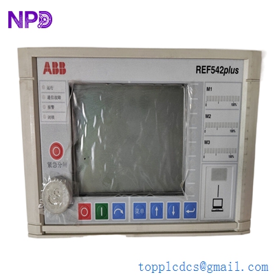

Description
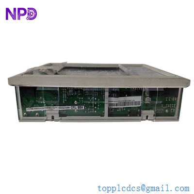
- Model: REF542plus (also written as REF542+)
- Brand: ABB (Switzerland/Germany)
- Series: Multiline Protection & Control Series
- Core Function: Combined protection, control, measurement, and monitoring for medium-voltage switchgear.
- Condition: Brand New Surplus (Original factory packaging, zero hours of operation).
- Product Type: Multifunction Feeder Terminal / Protection Relay.
- Key Specs: Large LCD Display | Ethernet/Modbus/IEC 61850 | Modular I/O.

ABB REF542plus
Key Technical Specifications
- Nominal Voltage (Un / Vn ): 100 V / 110 V / 230 V AC/DC (Wide-range power supply)
- Nominal Frequency: 50 Hz / 60 Hz (Software selectable)
- Analog Inputs: Up to 8 Current/Voltage sensors or CTs/VTs
- Binary Inputs/Outputs: Modular design (typically 14 to 42 I/O points)
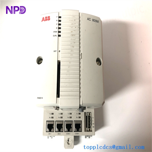
- Communication Protocols: IEC 61850, Modbus TCP/RTU, Profibus DP, LonTalk
- Protection Functions: 50/51 (OC), 51N (Earth Fault), 27/59 (Voltage), 81 (Frequency), 67 (Directional)
- Display: Integrated HMI with programmable function keys and mimic diagram
- Measurement Accuracy: Class 0.5 for voltage and current
- Operating Temperature: -5°C to +55°C
- Mounting: Flush mounted in switchgear door (IP54 front protection)
Installation & Configuration Guide
Phase 1: Pre-Installation (Preparation)
Critical Safety Checks:
- CT Shorting: Before removing an existing REF542plus, short-circuit all CT secondary terminals. An open CT circuit under load can cause high-voltage arcing and equipment destruction.
- Configuration Backup: Use the ABB FUPLA (Function Plan) programming tool or the SCU (Smart Configuration Unit) software to extract the existing configuration file (.r5p).
- Hardware Check: Ensure the “Order Code” on the new unit matches the old one. The REF542plus is highly modular; a mismatch in the “Slot 1” or “Slot 2” cards will cause hardware initialization errors.
Phase 2: Removing the Old Relay
- Isolate Power: Switch off the auxiliary DC supply.
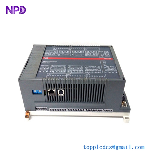
- Unplug Terminals: The REF542plus uses removable compression terminals. Unscrew the retaining screws and pull the terminal blocks out—do not disconnect the individual wires unless the terminal block itself is damaged.
- Mechanical Release: Loosen the four side clamps that hold the relay body to the switchgear door panel.
Phase 3: Hardware Installation
- Panel Mounting: Slide the new REF542plus into the 162mm x 245mm cutout. Secure the side clamps until the front gasket is tight.
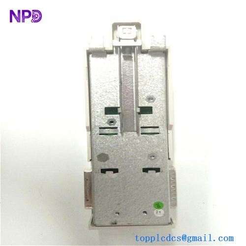
- Grounding: Connect the dedicated earth stud on the rear of the metal housing to the switchgear’s main ground bar. This is essential for EMI/RFI shielding.
- Reconnect Terminals: Plug in the terminal blocks. Match the numbering on the wire labels to the silk-screened numbers on the relay’s backplane.
Phase 4: Software & Commissioning
- Power On: The green “Ready” LED should light up. If the red “Internal Error” LED glows, check the module seating.
- Download Config: Connect your PC to the front RJ45 port or the rear communication port. Download the backed-up .r5p file using the ABB Configuration Tool.
- Binary I/O Test: Use the “Test Mode” to manually toggle the output relays (e.g., Trip, Close, Alarm) to ensure the wiring to the circuit breaker is intact.
- Analog Verification: Compare the current and voltage readings on the LCD with a secondary meter to ensure the CT/VT ratios are correctly set.
Customer Cases & Industry Applications
Case 1: Data Center Substation Emergency Recovery A tier-3 data center in Singapore faced a “Module Fail” alarm on the main incoming feeder relay (REF542plus). The facility was running on a single-feed risk. ABB’s standard lead time for a configured unit was 8 weeks. We supplied a New Surplus REF542plus within 48 hours. The client’s engineers transferred the logic via FUPLA, and the system was fully redundant again within 3 days.
Case 2: Steel Mill Directional Protection Fix In a heavy industrial steel mill, a refurbished relay from a local repair shop kept failing due to high harmonic distortion in the power supply. We provided an Original New Surplus unit. Unlike the “repaired” units, the new hardware had fresh filter capacitors and calibrated sensors. The directional overcurrent (67) nuisance trips stopped immediately, preventing an estimated $50,000 per hour in lost production time.
Frequently Asked Questions (FAQ)
Q: What is the difference between REF542 and REF542plus? A: The “plus” version is the updated hardware platform. It features a faster processor, improved communication options (like IEC 61850), and a larger memory capacity for fault recording. While the physical cutout is the same, the internal I/O modules are often not cross-compatible between the old REF542 and the REF542plus.
Q: Can I change the communication protocol from Modbus to IEC 61850? A: This depends on the communication card installed in the rear slot. If you have the Ethernet module, it is a software configuration change. If you have a serial-only card, you will need to swap the hardware module. We stock these separate communication cards if you need to upgrade.
Q: Does it come with the LCD display attached? A: Yes, our units are typically “Integrated” versions where the HMI and the base unit are one piece. If you need the “Detached HMI” version (where the screen is connected by a cable to the relay inside the cabinet), please specify that in your inquiry.
Q: Is the programming software included? A: We sell the hardware only. However, the configuration software (ABB REF542plus Configuration Tool) is generally available to licensed ABB partners and end-users. We can provide the technical manuals and wiring diagrams in PDF format.
Q: How do I know if this unit is “New Surplus”? A: Every REF542plus we ship comes with its original factory labels and serial numbers. You can verify the manufacture date with ABB. There will be no marks on the mounting lugs or scratches on the terminal screws—signs that the unit has never been installed in a live panel.