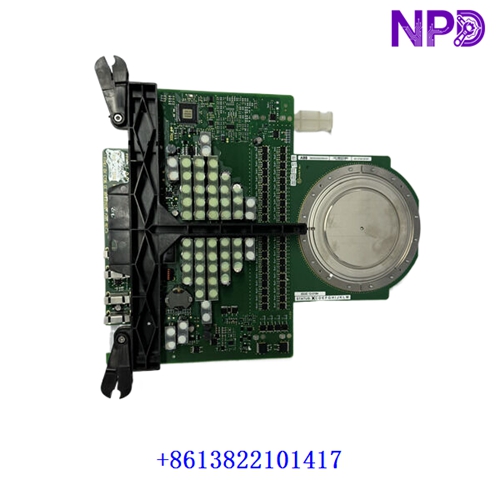

Description
This technical datasheet provides comprehensive specifications, installation procedures, routine maintenance guidelines, troubleshooting steps, safety precautions, and frequently asked questions for the ABB REL 551 MRK002480-AE line protection terminal. Engineered for high-voltage transmission line applications and distance protection schemes, this advanced numerical relay ensures reliable fault clearance and secure power system operation.
⚙ Product Technical Parameters
- 1. Brand: ABB
- 2. Model: REL 551 / MRK002480-AE
- 3. Series: Terminal Protection and Control (RET/REL Series)
- 4. Product Name: Numerical Distance Protection Terminal
- 5. Country of Origin: Sweden / Switzerland
- 6. Physical State: Microprocessor-based electronic hardware module
- 7. Dimensions: 177 mm × 281 mm × 204 mm (Modular 19-inch rack terminal chassis format)
- 8. Weight: 5.2 kg
- 9. Origin Location: European Union Production Facility
- 10. Power Consumption: 20W (Max operational draw under rated auxiliary DC voltage)
📋 Initial Operation Checklist
Before energizing the protection terminal for the first time, verify all physical and electrical configurations to prevent system maloperation or hardware failure:
- Inspect the terminal housing, rear multi-pin connectors, and optical communication ports for any transit damage.
- Confirm that the auxiliary DC supply voltage matches the internal power supply module rating with correct polarity.
- Verify that all current transformer (CT) and voltage transformer (VT) secondary wiring circuits are tightly secured and short-ing blocks are removed.
- Ensure ambient operating temperature falls within the specified environmental range of -10°C to +55°C.
- Check front-panel LCD contrast, binary input/output mapping, and initial setting group parameters prior to putting the line into service.
🛠 Routine Maintenance and Upkeep
Regular maintenance ensures optimal operational longevity and sustained reliability across critical high-voltage transmission lines:
- Perform bi-annual visual inspections to check for dust accumulation, environmental corrosion, or loose rear terminal screws.
- Clean the front-panel display and membrane keypad using a soft, dry lint-free cloth; avoid abrasive agents or chemical solvents.
- Conduct regular self-supervision status checks and review internal event logs to verify watchdog and memory integrity.
- Verify terminal block screw torque values yearly to prevent high-resistance connection faults caused by thermal cycling or vibration.
🔧 Troubleshooting and Common Issues
Systematic problem isolation minimizes downtime when operational anomalies occur in the substation environment:
- Display Panel Unlit / Unit Dead: Check external DC supply miniature circuit breakers (MCBs), measure input voltage at rear terminals, and verify power supply fuse status.
- Internal Watchdog (IRF) Alarm Triggered: Check error codes via the HMI event register, cycle auxiliary power, and ensure all internal printed circuit boards are firmly seated.
- Distance Protection Misoperation: Verify VT/CT ratio programming settings, check phase angle alignments, and inspect secondary circuit loop integrity.
- Communication Link Failure: Check fiber-optic patch cables, verify baud rate and protocol parameters, and test optical transceiver signal strength.
🛡 Safety Precautions
Strict adherence to safety guidelines protects personnel from severe electrical hazards and prevents permanent hardware damage:
- Always short-circuit active current transformer (CT) secondary leads before disconnecting any wiring from the terminal backplane.
- Ensure all auxiliary power and tripping circuits are completely isolated, disconnected, and locked out before performing hardware service.
- Observe standard electrostatic discharge (ESD) wrist strap handling protocols when interacting with internal electronic modules.
- Ensure all field wiring complies strictly with local electrical safety codes, utility standards, and manufacturer specifications.
❓ Frequently Asked Questions (Q&A)
- Q1: Can setting groups be switched remotely while the transmission line is energized?
- A1: Yes, active setting groups can be switched remotely via binary inputs or communication commands, provided the terminal is configured and authorized for remote group selection.
- Q2: What does a steady red fault indicator on the front panel imply?
- A2: A steady red internal relay failure (IRF) LED indicates that the built-in self-supervision system has detected an unrecoverable hardware or software fault, requiring immediate unit inspection or replacement.
- Q3: Does the REL 551 terminal support event and disturbance record extraction?
- A3: Yes, the unit features internal non-volatile memory capable of storing comprehensive event logs, fault time tags, and analogue disturbance recordings accessible via local or remote software tools.