
Description
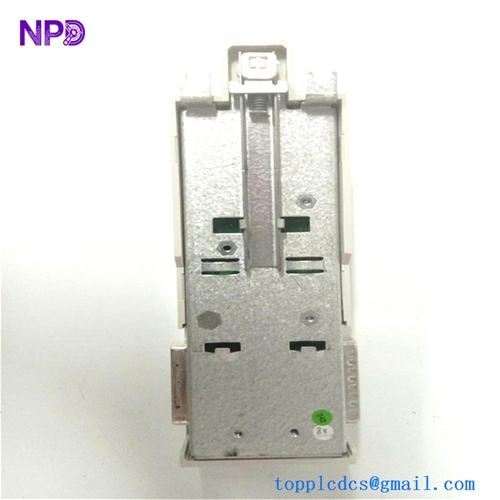
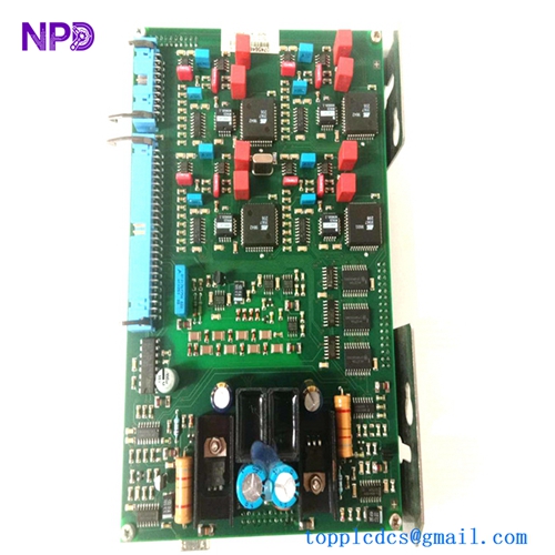
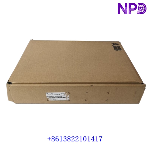
This technical datasheet provides comprehensive specifications, installation procedures, routine maintenance guidelines, troubleshooting steps, safety precautions, and frequently asked questions for the ABB SDCS-FEX-3.A REV.D (3ADT312400R0001) speed control motherboard. Engineered for industrial DC drive and automation systems, this high-performance component ensures precise motor regulation, feedback processing, and reliable drive control management.

⚙ Product Technical Parameters
- 1. Brand: ABB
- 2. Model: SDCS-FEX-3.A / 3ADT312400R0001 (REV.D)
- 3. Series: DCS / Industrial DC Drive Control Series
- 4. Product Name: Speed Control Motherboard / Field Exciter Control Board
- 5. Country of Origin: Switzerland / Germany
- 6. Physical State: Multi-layer surface-mount printed circuit board assembly
- 7. Dimensions: Standard modular drive rack-insert format
- 8. Weight: 0.75 kg
- 9. Origin Location: European Manufacturing Facility
- 10. Power Consumption: 12W (Max operational control draw under internal DC supply rails)
📋 Initial Operation Checklist
Before installing and energizing the speed control motherboard for the first time, verify all physical and electrical configurations to prevent system faults or hardware damage:
- Inspect the PCB traces, components, and edge connectors carefully for any transit damage, micro-cracks, or dust contamination.
- Confirm that the main drive power supply is completely de-energized, locked out, and that internal DC link capacitors are fully discharged.
- Verify that all plug-in ribbon cables, multi-pin connectors, and slot guides are properly aligned and securely seated.
- Ensure ambient operating temperature within the drive cabinet remains strictly between -10°C and +55°C.
- Check jumper settings, hardware version tags, and parameter configurations against your specific drive architecture prior to startup.
🛠 Routine Maintenance and Upkeep
Regular maintenance ensures optimal operational longevity and sustained reliability across industrial DC drive architectures:
- Perform bi-annual visual inspections to check for dust accumulation, cabinet moisture, or corrosion on terminal blocks and connectors.
- Clean board surfaces gently using a clean, dry, anti-static brush or compressed air; strictly avoid chemical solvents, sprays, or liquids.
- Monitor system diagnostic logs and error counters periodically during scheduled plant maintenance intervals.
- Check chassis mounting screws and terminal connectors annually to prevent loose connections caused by thermal expansion or vibration.
🔧 Troubleshooting and Common Issues
Systematic problem isolation minimizes downtime when operational anomalies or control faults occur:
- Board Initialization Failure: Check internal DC supply voltage rails, verify connector seating, and inspect status LED indicators.
- Communication or Speed Feedback Loss: Inspect encoder or tachogenerator wiring, check signal shielding integrity, and verify parameter scaling.
- Drive Trip / Overcurrent Alarm: Check control signal stability, examine feedback loops, and ensure proper grounding of the drive enclosure.
- Intermittent System Resets: Check for electromagnetic interference (EMI) sources near signal routing and confirm proper cabinet shielding.
🛡 Safety Precautions
Strict adherence to safety guidelines protects personnel from severe electrical hazards and prevents permanent hardware damage:
- Always disconnect and lock out main high-voltage AC and DC power sources before servicing or replacing drive electronics.
- Observe standard electrostatic discharge (ESD) wrist strap handling protocols when interacting with sensitive printed circuit boards.
- Ensure all DC link and converter power capacitors are fully discharged down to safe voltage levels before touching internal components.
- Ensure all wiring and grounding comply strictly with local electrical codes, industrial safety standards, and manufacturer recommendations.
❓ Frequently Asked Questions (Q&A)
- Q1: Does this replacement motherboard require parameter reconfiguration after installation?
- A1: Yes, specific drive parameters, calibration data, and software configuration settings must be verified or restored via the control panel or engineering software tool to match application requirements.
- Q2: Can this board be replaced while the drive system is active?
- A2: No, replacing internal control motherboards requires a complete system shutdown, power isolation, and capacitor discharge to prevent severe electrical shock and component destruction.
- Q3: What should I do if a fault code persists after installing the replacement board?
- A3: Verify that all internal connectors and ribbon cables are firmly locked in place. Check the event logger via the control software to isolate whether the fault originates from the board or external peripheral devices.