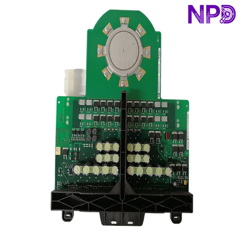

Description
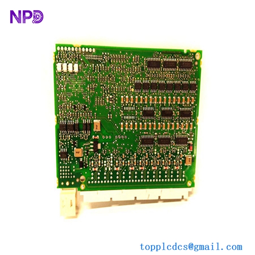
The ABB SDCS-IOB-21 is a specialized Input/Output (I/O) interface board primarily used within the DCS800 and DCS500 series of DC industrial drives. This module functions as the bridge between the drive’s main control unit and the external field environment, allowing the drive to communicate with sensors, limit switches, and peripheral actuators. It is a critical component for motor control applications where real-time discrete I/O and analog signal processing are required for machine synchronization and safety.
Product Specifications
📍 Product Series: ABB DCS Drive Series (DCS800/DCS500)
⚖️ Weight: 0.35 kg
📏 Dimensions: 200 mm x 150 mm x 20 mm
🌍 Country of Origin: Finland / Germany
⚡ Operating Voltage: 24 V DC (System bus powered)
🔄 I/O Capacity: Digital Inputs/Outputs and Analog Channels
🛡️ Protection Class: IP00 (Requires mounting inside drive chassis)
🌡️ Operating Temperature: 0°C to +55°C
🏗️ Mounting Type: Integrated drive control rack / card slot
🔌 Interface: Multi-pin plug-in terminal blocks / Internal drive bus connector
Technical Architecture
The SDCS-IOB-21 is designed to handle signal conditioning for various industrial feedback types. By utilizing optical isolation on the input channels, the board protects the drive’s sensitive control electronics from electrical noise or voltage spikes generated by field devices. Understanding the board’s signal flow is essential for commissioning or diagnosing motor control issues.
Recommended Components and Services
🔍 SDCS-IOB-22: Variant with expanded analog output capability.
🔍 SDCS-IOB-21-R: Factory-refurbished certified unit.
🔍 DCS800-Control-Unit: Main processor module that pairs with the IOB-21.
🔍 SDCS-PIN-Kit: Replacement terminal block connector set for IOB-21.
🔍 ABB-Drive-Window-Software: Tool for configuring and mapping the I/O channels of the SDCS-IOB-21.
🔍 SDCS-IOB-Shield: Protective EMI shroud for reducing signal noise.
🔍 DCS-Drive-Rack-Backplane: Spare board interface slot for drive expansion.
🔍 SDCS-IOB-Diagnostic-Test-Board: Hardware used to simulate signal inputs for troubleshooting.
🔍 Component-Level-Repair-Service: Restoration of I/O boards (capacitor/relay replacement).
🔍 DCS800-Hardware-Manual: Official documentation for signal mapping and pinout diagrams.
Maintenance and Diagnostic Tips When troubleshooting I/O failures on the SDCS-IOB-21, follow these steps:
- Check Field Power: Ensure the external 24V DC supply used for sensors is stable, as ground loops on this line are a common source of “flickering” I/O status in the software.
- Inspect Connectors: The high-vibration environment of a drive cabinet can lead to loose connections; ensure all terminal blocks are securely seated.
- Mapping Check: If an input is not triggering in the PLC, verify that the signal is correctly mapped in the drive’s parameter configuration.