Description
- Model/Type Designation: ABB UAC389AE02
- Product ID/Part Number: HIEE300888R0002
- Brand: ABB (Asea Brown Boveri)
- System Control Architecture: ABB Variable Frequency Drive (VFD) / Industrial Drive Auxiliary Control Frameworks.
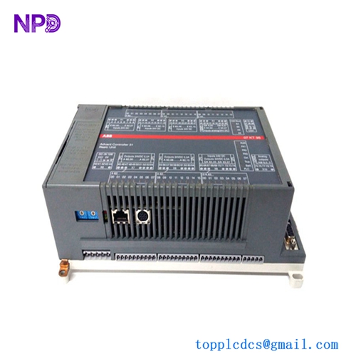
- Core Function: Auxiliary control and signal interface board. This module facilitates low-voltage logic signal routing, status feedback telemetry, and I/O coordination between the drive’s main control processor and external auxiliary monitoring/control panels.
- Condition: Brand New Surplus (Original factory-authorized authentic stock, zero field execution hours, unconfigured)
- Product Type: Auxiliary Control Interface / Signal Processing Board
- Operating Input Voltage: 24 V DC internal logic rail
- Signal Handling: Multi-channel auxiliary digital I/O routing
- Isolation: Galvanic and optocoupler isolation for digital interface lines to prevent ground-loop interference
- Processing: Onboard signal conditioning for status telemetry and logic synchronization
- Communication Interface: High-speed backplane connector for integration with main drive processor units
- Operating Ambient Temperature: -20°C to +70°C maximum control cabinet environment limits
- Storage Temperature Window: -40°C to +85°C structural envelope limits
- Atmospheric Moisture Limits: 5% to 95% relative humidity (RH, non-condensing)
- Mounting Configuration: Designed for direct integration into ABB industrial drive control chassis
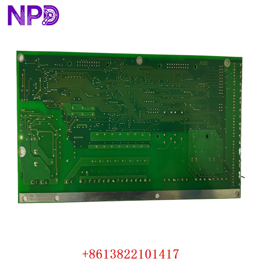
ABB UAC389AE02 HIEE300888R0002
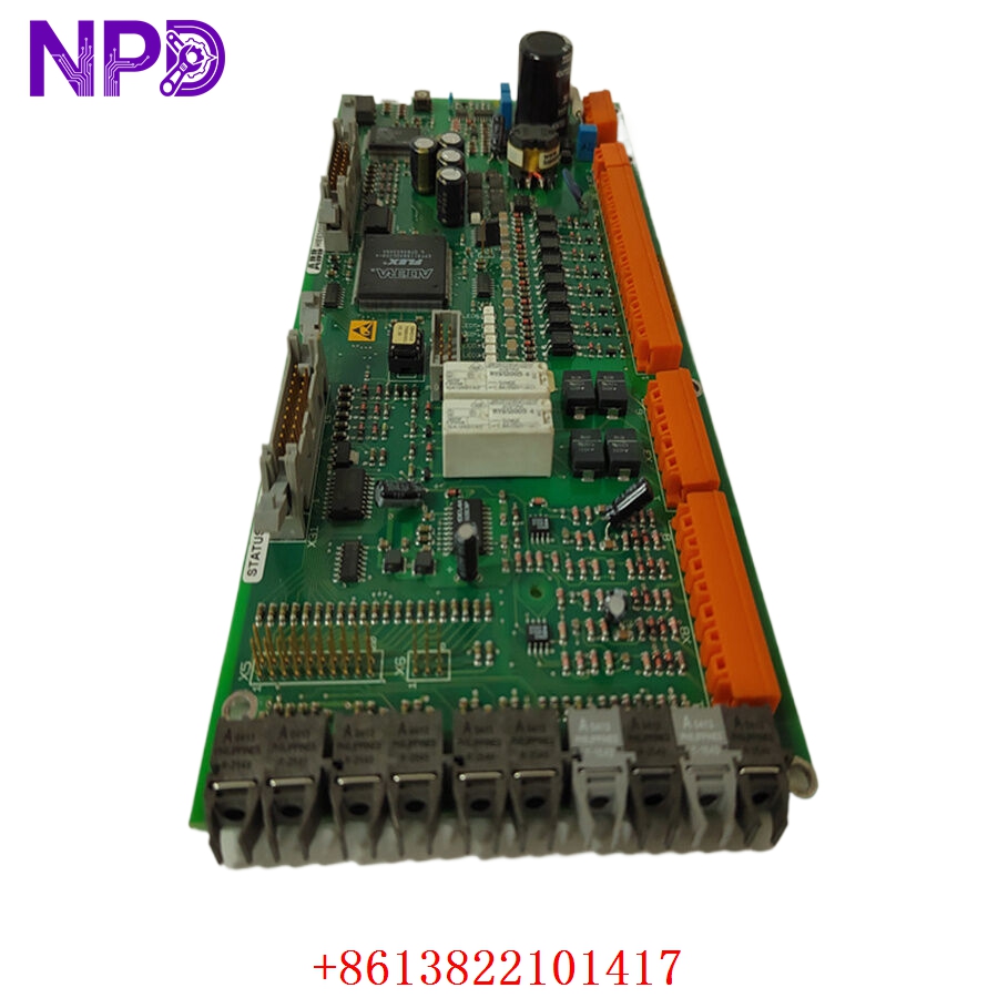
ABB UAC389AE02 HIEE300888R0002
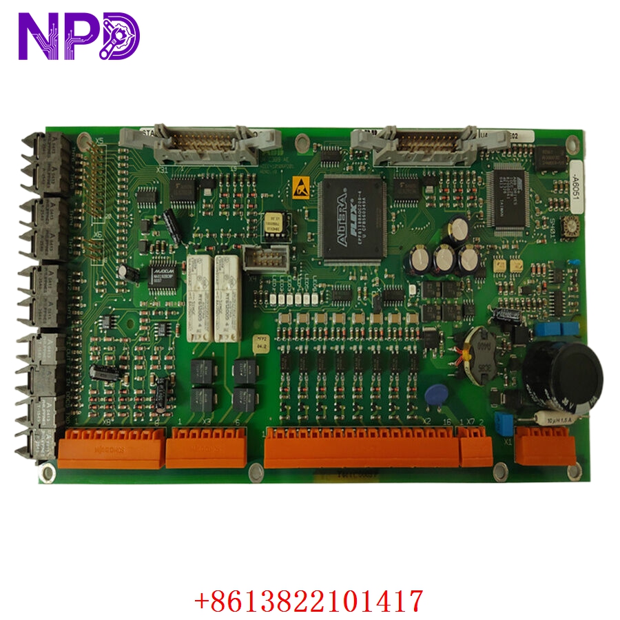
ABB UAC389AE02 HIEE300888R0002
Installation & Configuration Guide
Pre-Installation Setup
⚠️ CRITICAL SAFETY WARNING:
- Coordinate a complete bypass profile with your site safety supervisor. Replacing an auxiliary interface card while the drive is energized can trigger an unexpected system state transition or trip high-voltage breakers.
- DANGER: HIGH VOLTAGE LETHAL RISK. Isolate and lock out (LOTO) all main multi-kilovolt power lines feeding the drive. Verify that all DC link bus capacitors are fully discharged before access.
- Verify proper cabinet grounding to protect sensitive logic components.
- Required Tools & Gear:
- Grounded anti-static wrist strap anchored to the cabinet frame.
- Standard 4.5 mm flathead screwdriver and Pozidriv PZ1 tool array.
- ABB drive management software suite for parameter verification.
- Backup Procedures:
- Connect to the drive controller and download a full parameters backup file. This ensures your configuration is preserved if the auxiliary board holds status mapping.
- Document the physical layout of all ribbon cables and jumpers.
Old Board Removal
- Verify Isolation: Confirm high-voltage isolators are locked out and DC link bus capacitors are discharged.
- Label/Disconnect: Label and unplug all ribbon cables, optical links, and terminal plugs connected to the board faceplate.
- Hardware Removal: Back out the captive screws securing the control board to the chassis.
- Extraction: Carefully lift the board from its alignment rails, avoiding contact with adjacent modules. Place it on an ESD-protected surface.
New Board Mounting and Configuration
- ESD Mitigation: Wear a grounded anti-static wrist strap when opening the protective packaging of the UAC389AE02 / HIEE300888R0002 board.
- Replicate Settings: Check jumpers or switches on the new board to ensure they match the original module’s configuration.
- Chassis Alignment: Position the board into the mounting standoffs within the control section.
- Secure: Tighten the retaining screws to ensure solid chassis contact.
- Reconnect: Reattach all cables and plugs, ensuring all connectors click securely into place.
Frequently Asked Questions (FAQ)
Q1: What is the relationship between HIEE300888R0002 and UAC389AE02?
A: Model UAC389AE02 is the functional designation for this interface card, while HIEE300888R0002 is the unique ABB manufacturing product ID. Both identify the same physical hardware.
Q2: Do I need to program this board after installation?
A: No. This module is hardware-driven and inherits its configuration from the main drive controller’s existing parameter file. Once installed, it automatically functions based on the logic established in the drive’s parameters block.
Q3: How is the quality of these surplus parts verified?
A: We test every module using a dedicated ABB drive test chassis. We perform a 24-hour stress test, simulating digital I/O signal sequences to ensure all optocouplers and signal paths operate within factory specifications before shipment.
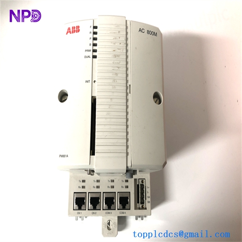
Q4: What do red/amber status LEDs indicate?
A: Status LEDs provide real-time feedback. If you observe red/amber lights after installation, ensure the board is fully seated and that the drive’s control software correctly recognizes the module.
Q5: What payment and shipping methods are available for emergency repairs?
A: We accept wire transfers (T/T), corporate credit cards, and letters of credit. For unplanned outages, send us a copy of your bank’s wire transfer confirmation, and we will immediately process, test, and ship the part via express air (DHL/FedEx).
Do you have the specific drive parameter manual for this auxiliary module, or would you like assistance in identifying the specific pinout configuration for your installation?