Description
- Model: ABB UAD149 (3BHE014135R0011)
- Brand: ABB (Switzerland)
- Series: UNITROL® / MEGATROL Power Electronics Systems
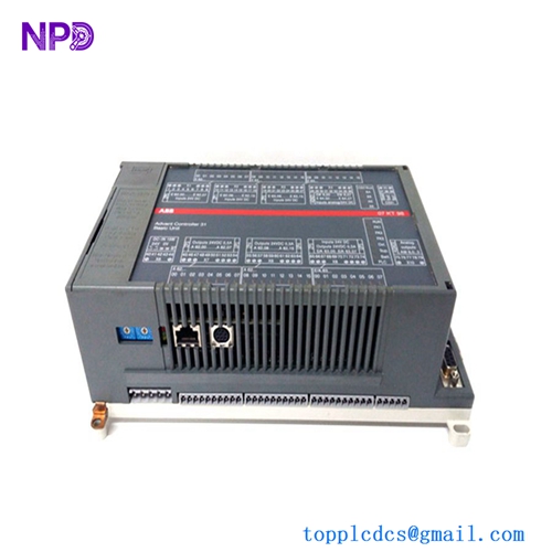
- Core Function: High-speed control and interface module for excitation systems
- Product Type: Control Unit / Printed Circuit Board Assembly
- Key Specs: UAD149A00-0-11 variant 24V DC Internal Logic Fiber Optic/Serial Comms
Key Technical Specifications
- Voltage Rating: Standard 24 V DC internal logic supply
- Hardware Revision: A00-0-11 (Specific high-reliability variant)
- Communication: Support for internal high-speed bus and fiber optic links
- Compatibility: Used primarily within UNITROL 6000 and MEGATROL series
- I/O Interface: Dedicated pins for analog/digital pulse feedback
- Protection: Coated PCB for resistance to industrial humidity and dust
- Mounting: Rack-mounted or carrier-integrated depending on the cabinet design
- Processor: Integrated high-speed DSP for real-time excitation control
- Diagnostics: On-board LED status indicators for power, run, and fault states
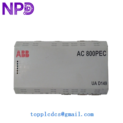
ABB UAD149 3BHE014135R0011 UAD149A00-0-11-4
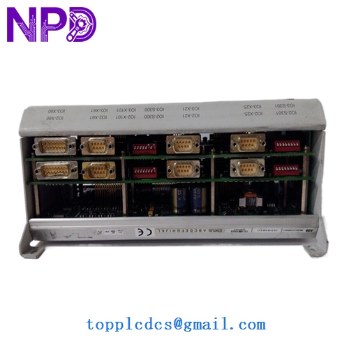
ABB UAD149 3BHE014135R0011 UAD149A00-0-11-4
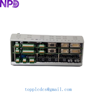
ABB UAD149A0011 3BHE014135R0011
Installation & Configuration Guide
Phase 1: Preparation (Pre-Installation)
Estimated time: 20 minutes
⚠️ Safety Warning:
- This module is part of the generator excitation system. Shutdown and isolation of the excitation transformer are mandatory.
- High voltage may be present on adjacent busbars. Verify zero voltage with a calibrated meter.
- Handle the UAD149 only by the edges. The surface-mount components are highly sensitive to ESD.
Requirements:
- Full system backup of the excitation parameters.
- ESD-safe toolkit and wrist strap.
- Flashlight and mirror for checking rear connector alignment.
Phase 2: Removal & Address Matching
Estimated time: 15 minutes
Step 1: Record Cable Positions Before disconnecting, label every fiber optic cable and ribbon connector. I recommend taking three high-resolution photos: one for the wiring, one for the DIP switches, and one for the jumpers.
Step 2: Jumper Configuration Check the jumpers on the new 3BHE014135R0011 against the old board. These often control signal levels or termination resistors. If they don’t match, the board may fail to communicate or produce incorrect pulse outputs.
Phase 3: Insertion & Software Download
Estimated time: 25 minutes
- Insertion: Slide the board into the slot, ensuring the backplane pins engage smoothly. Do not force it; if there is resistance, check for bent pins.
- Fiber Optics: Carefully re-insert the fiber optic cables. Ensure the “Click” is heard to guarantee a solid light path.
- Power Up: Energize the control supply. The “Power” LED on the UAD149 should be solid.
- Firmware/Parameter Load:
- Connect the PC tool (e.g., ControlIT or CMT).
- Verify the board is recognized.
- If the board is “Blank,” you must download the specific excitation parameters and firmware version that matches your generator’s profile.
Customer Cases & Industry Applications
Case 1: Hydropower Plant Excitation Failure A hydropower station in South America faced a total unit trip when a UAD149 board failed, leading to a “Loss of Excitation” alarm. The OEM quoted a lead time of 16 weeks. We supplied a New Surplus 3BHE014135R0011 from stock. It was delivered and commissioned within 6 days. The plant avoided nearly three months of lost generation revenue, which would have exceeded $500,000.
Case 2: Gas Turbine Control Refresh During a major overhaul (C-Inspection) of a gas turbine, the maintenance team discovered oxidation on the excitation control bus. To ensure another 10 years of reliable operation, they decided to replace the critical control boards. We provided two UAD149A00-0-11 modules. Because these were New Surplus, they provided the longevity of a new part at a significantly lower cost, fitting perfectly into the turnaround budget.
Frequently Asked Questions (FAQ)
Q: What does the “A00-0-11” suffix signify? A: This refers to the specific hardware configuration and pre-loaded base firmware capability. In my experience, even if your current board is an “A00-0-10,” the A00-0-11 is usually the improved, backward-compatible replacement. However, we always recommend verifying the compatibility with your specific UNITROL version.
Q: Does this board require a battery? A: The board itself relies on the system’s non-volatile memory and auxiliary 24V supply. However, if your system uses a specific memory backup module, check that separately. The UAD149 is primarily a processing and interface board.
Q: Why is fiber optic communication used on this board? A: Excitation systems involve high-voltage switching and high EMI (Electromagnetic Interference). Fiber optics provide total electrical isolation, preventing noise from the power bridge from corrupting the sensitive logic on the 3BHE014135R0011.
Q: How do you verify the board is “New Surplus”? A: We inspect the board for any “heat soak” discoloration—a common sign of used boards. The solder joints are checked for original factory luster, and the gold fingers are inspected for insertion scratches. We only ship boards that pass this 10-point physical and electrical inspection.
Q: Can I change the board without a PC tool? A: It’s risky. While some systems can “push” parameters from the master controller to a new slave board, you generally need the ABB configuration software to verify the firmware version and ensure the board is fully synchronized with the rest of the excitation rack.