Description
- Model: UFC721BE101 (3BHE021889R0101)
- Brand: ABB (Switzerland)
- Series: UNITROL 6000 / UNIGLYPH series
- Core Function: High-performance control and firing pulse electronics for power converters
- Product Type: Controller Board / Pulse Processor (New Surplus)
- Key Specs: Integrated FPGA logic | High-speed fiber optic communication | Precise gate pulse timing
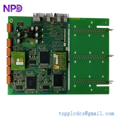
ABB UFC721BE101 3BHE021889R0101
Key Technical Specifications
- Order Code: 3BHE021889R0101
- Hardware Revision: BE101 (Enhanced signal integrity build)
- Application: Excitation systems (UNITROL 6000) and Large Drive frequency converters
- Communication Interface: Multiple high-speed fiber optic channels for EMI-immune data transfer
- Logic Processing: Onboard FPGA for nanosecond-level firing pulse accuracy
- Power Supply: Dedicated DC-DC conversion for internal logic stability
- Diagnostic Features: Front-panel LED array for real-time status and fault detection
- Compatibility: Works with COB (Communication Board) and CIO (Control I/O) modules
- Operating Temp: -5 °C to +60 °C (Standard cabinet deployment)
- Isolation: Reinforced galvanic isolation between control and power stages
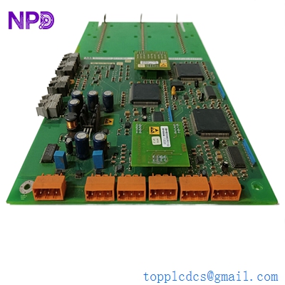
ABB UFC721BE101 3BHE021889R0101
Installation & Configuration Guide
Phase 1: Preparation (Pre-Installation)
⚠️ Safety First:
- This board controls power converters. Ensure the DC link is fully discharged and the generator is at a complete standstill.
- Backup: Record the current firmware version and parameter set from the <i>Local Control Panel (LCP)</i>.
- ESD Protocol: Always use a grounded wrist strap. The FPGA and optical transceivers on the UFC721BE101 are extremely sensitive to static discharge.
Phase 2: Removal of Faulty Module
- Fiber Optic Handling: Disconnect the fiber optic cables carefully. Do not bend them beyond a 50 mm radius. Use dust caps on the disconnected fibers and board ports immediately.
- Mounting: Unscrew the retaining fasteners from the 19-inch rack frame.
- Extraction: Pull the board straight out using the handles. Avoid touching the gold fingers on the backplane connector.
Phase 3: New Module Installation
- Flash Check: Verify if the new 3BHE021889R0101 requires a firmware upload. In many UNITROL systems, the firmware resides on a separate memory module or is downloaded from the master controller.
- Insertion: Align the PCB with the card guides and push firmly until the DIN connector is fully seated.
- Connectivity: Reconnect the fiber optics. Ensure the “click” is felt. Crossing the “Transmitter” and “Receiver” fibers is a common mistake—double-check the labels.
Phase 4: Commissioning & Testing
- Power-On: Switch on the control power. The “Power” LED should be solid, and the “Fault” LED should turn off after a brief self-test.
- Software Sync: Use the ABB <i>Control Builder</i> or <i>Excitation Tool</i> to verify that the board is communicating with the main AC 800PEC controller.
- Pulse Test: Conduct a “Dry Run” or “Gate Pulse Test” without main power applied to verify that firing pulses are reaching the thyristor bridge correctly.
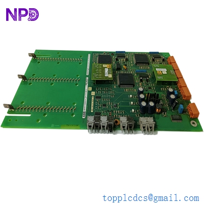
ABB UFC721BE101 3BHE021889R0101
Customer Cases & Industry Applications
Case 1: Sudden Trip in a Nuclear Power Plant Excitation System
Situation: A nuclear facility in France experienced an unscheduled trip of their backup generator due to a “Pulse Missing” error. The failure was traced to the UFC721BE101 board responsible for the thyristor firing sequence in the UNITROL 6000 system.
Task: The plant had to restore the generator to “Ready” status within 72 hours to comply with safety regulations. ABB’s standard lead time for this specific revision was over 8 weeks.
Action: We provided a New Surplus 3BHE021889R0101 revision BE101. The board was air-freighted immediately and arrived at the facility the next day.
Result: The onsite engineering team swapped the board and synchronized it with the master controller. The generator passed its load test on the first try. The maintenance lead noted: “Having access to a brand-new revision-matched board saved us from a significant regulatory headache.”
Case 2: Redundancy Restoration in a Mining Drive System
Situation: A large copper mine in Chile used ABB Megadrive-LCI units for their ore crushers. One of the redundant control channels failed when a UFC721BE101 board malfunctioned due to excessive vibration and dust ingress.
Task: While the mine continued to operate on the single remaining channel, the risk of a total production halt was high. They needed a high-reliability replacement, not a used or repaired unit that might fail under the harsh site conditions.
Action: We supplied two units: one for immediate replacement and one for the mine’s strategic spares locker. These were New Surplus, meaning the internal components had zero “operational hours” of heat stress.
Result: Redundancy was restored within the shift. The mine manager decided to standardize their spare parts sourcing through us for all legacy UNITROL and LCI electronics to avoid future “Single Point of Failure” risks.
Frequently Asked Questions (FAQ)
Q: What does the “BE101” suffix represent? A: In ABB’s system, the suffix (like BE101) represents the hardware revision level. “BE” usually indicates a specific hardware configuration or minor component update. Our 3BHE021889R0101 boards are the BE101 revision, which is highly stable and widely used in the UNITROL 6000 series.
Q: Can I use a UFC721AE version to replace a BE101? A: I wouldn’t recommend it. While they look identical, the “AE” and “BE” revisions often have different FPGA gate-ware or timing constants. Mixing revisions in a redundant system can cause “Voter Disagreement” errors. It is always safest to match the R-number and the suffix exactly.
Q: Why is fiber optic used for the pulse signals? A: Excitation systems generate massive amounts of Electromagnetic Interference (EMI) because of the high currents being switched. Fiber optics are immune to this interference, ensuring that the firing pulses reach the thyristors with microsecond precision without being distorted by noise.
Q: Does this board come pre-loaded with site parameters? A: No. The UFC721BE101 is a hardware platform. The specific control parameters (like firing angles and current limits) are stored in the system’s non-volatile memory and are loaded onto the board during the boot-up sequence.
Q: How do you know the board is “New”? A: We verify the original ABB factory seals and the “Manufacturing Date” on the PCB. “New Surplus” means it has sat in a box as a spare and has never seen a live electrical load. This is critical for power electronics, where heat is the primary killer of components.