
Description
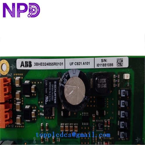
- Model: ABB UFC921A101
- Associated Part Numbers: 3BHE024855R0101 (Module Assembly) / 3BHE024856P201 (PCB Level)
- Brand: ABB (Switzerland)
- Series: UNITROL® 6000 Power Electronics
- Core Function: High-speed communication interface and signal processing for excitation systems
- Product Type: Communication / Control Module
- Key Specs: Multi-channel fiber optic support Low-latency data bus Integrated diagnostics
Key Technical Specifications
- Application: Primary communication gateway for UNITROL 6000 excitation control racks
- Data Links: Multiple fiber optic (FO) ports for EMI-immune data transmission
- Hardware Rev: 3BHE024856P201 (Ruggedized PCB revision)
- Protocol Support: Proprietary high-speed internal bus for synchronizing TMR (Triple Modular Redundant) controllers
- On-board Processing: Dedicated FPGA/DSP for real-time signal management
- Indicators: Front-panel LEDs for Status, Link/Activity, and Error states
- Power Consumption: Optimized for low heat dissipation in high-density racks
- Coating: Fully tropicalized (conformal coated) for harsh industrial environments
- Compatibility: Seamlessly integrates with UAD and USC series control modules
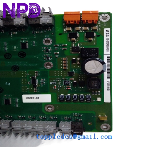
ABB UFC921A101 3BHE024855R0101 3BHE024856P201
ABB UFC921A101 3BHE024855R0101 3BHE024856P201
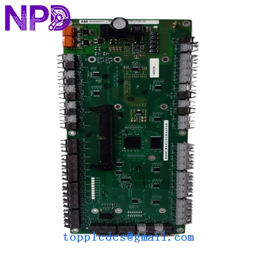
ABB UFC921A101 3BHE024855R0101 3BHE024856P201
Installation & Configuration Guide
Phase 1: Preparation (Pre-Installation)
Estimated time: 15 minutes
⚠️ Safety Warning:
- This module handles critical data for generator excitation. A failure here can lead to a “Loss of Sync” or “Over-excitation” trip. Ensure the system is in a safe “Off” or “Local” state.
- Static electricity is the primary killer of the UFC921A101. Use a grounded ESD mat and wrist strap.
- Inspect the fiber optic ports on the new module for any dust caps; do not remove them until the moment of connection.
Required Items:
- Fiber optic cleaning kit (pen-type cleaner or lint-free wipes).
- ABB CMT (Commissioning and Maintenance Tool) software.
- ESD-safe handling equipment.
Phase 2: Fiber Optic Link Verification
Estimated time: 10 minutes
Step 1: Inspect Cables Before removing the old board, verify the light levels of the fiber links if the system is still powered. A weak light signal often mimics a board failure.
Step 2: Port Assignment The UFC921A101 has multiple FO ports. Label each cable (TX/RX and Port Number) clearly. Swapping these during installation will result in a “Communication Timeout” alarm.
Phase 3: Replacement & Synchronization
Estimated time: 20 minutes
- Extraction: Release the retaining screws and pull the module out using the ejector handles.
- Insertion: Slide the new 3BHE024855R0101 into the guide rails. Ensure the backplane DIN connector seats fully without excessive force.
- Connectivity: Reconnect fiber optics and any copper serial links.
- Boot-Up:
- Energize the control rack.
- The “Power” and “Boot” LEDs should cycle.
- Once the “Link” LEDs turn solid green, the module has established a handshake with the controller.
- Firmware Check: Use the CMT tool to verify the firmware on the UFC921A101 matches the rest of the control cluster.
Customer Cases & Industry Applications
Case 1: Hydroelectric Plant Communication Fault A 200MW hydro plant in Canada suffered intermittent “Inter-module Bus” errors, causing the excitation system to drop out of redundancy. The culprit was a degraded communication chip on the original UFC921 board. We provided a New Surplus UFC921A101 via 3-day express. The module was replaced during a short outage, and the TMR system resumed full redundant operation immediately.
Case 2: Steel Mill Power Quality Stabilizer A steel mill using a Static Var Compensator (SVC) with UNITROL 6000 technology needed to replace a module damaged by a cooling fan failure (overheating). The UFC921A101 was essential for syncing the firing pulses across multiple power blocks. Our ability to ship the 3BHE024855R0101 from stock saved the client a 14-week OEM lead time, keeping the mill’s power factor within utility compliance limits.
Frequently Asked Questions (FAQ)
Q: Does UFC921A101 require a software “IP Address” setup? A: No. It operates on a proprietary high-speed internal bus. While it has unique IDs within the rack, these are typically set via physical rotary switches or DIP switches on the board or inherited from the slot position.
Q: Can I swap this module while the generator is online? A: Only if your system is configured for Hot-Standby redundancy. If you have a single-channel system, pulling the UFC921A101 will break the communication loop and trip the excitation. In my experience, even in redundant systems, it’s safer to perform the swap during a scheduled maintenance window.
Q: What is the difference between R0101 and other R-versions? A: The “R” number represents the assembly revision. R0101 is a common, stable revision used in the majority of UNITROL 6000 applications. It is generally backward compatible with earlier R-versions, but always verify your specific system’s “Bill of Materials.”
Q: Why are there so many fiber optic ports? A: High-power excitation environments generate massive amounts of electrical noise. Fiber optics allow the UFC921A101 to communicate between control racks and power bridges without the risk of EMI-induced data corruption.
Q: How do I verify the module is “New Surplus”? A: We perform a visual “Gold Finger” inspection to ensure no insertion marks are present. Furthermore, we verify that all fiber optic port covers are intact and the conformal coating shows no “yellowing” typical of boards that have spent years in a hot cabinet. You get a clean, zero-hour module.