
Description
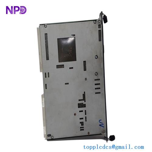
The DAIHATSU MEIYO ELECTRIC MDP-REVD is a high-precision speed switch unit, widely recognized for its reliability in monitoring and controlling rotational speed in marine and industrial engines. As a key component of the Daihatsu/Meiyo Electric automation suite, this device provides critical overspeed protection and operational speed management, ensuring engine integrity under varying load conditions.
📋 Technical Specifications
🔹 Product ID: MDP-REVD 🔹 Function: Rotational Speed Switch / Monitoring 🔹 Operating Voltage: Standard 24V DC 🔹 Input Signal: Frequency / Pulse (Magnetic Pickup) 🔹 Output Type: Relay Contact / Analog Signal 🔹 Weight: Approximately 0.9 kg 🔹 Origin: Japan
🚀 Application Fields
⚡ Marine Diesel Engine Overspeed Protection ⚓ Auxiliary Engine RPM Monitoring 🏭 Power Plant Generator Control ⚙️ Industrial Turbine Speed Supervision
🛠️ Product Instructions
The MDP-REVD unit is typically mounted within an engine control panel or a localized terminal box. Ensure the housing is sealed against oil mist and moisture. When connecting the pulse pickup sensor, use high-quality shielded cable to prevent frequency interference. Proper grounding is essential to eliminate electrical noise that could lead to erratic speed readings or false trips.
⚙️ Communication & Configuration Steps
⚙️ Address Mapping: This unit operates via direct analog/frequency signal processing rather than a network bus. Configuration is performed through internal physical switches or potentiometers. ⚙️ Station Number: Not applicable; integration is achieved via point-to-point wiring to the engine’s main control system. ⚙️ Baud Rate/Trigger Point: Configure the “Trip” and “Alarm” setpoints by adjusting the onboard multi-turn potentiometers. Use a calibrated frequency generator connected to the input terminals to verify the trigger thresholds before final commissioning.
🔋 Power-up Debugging Process
✅ Step 1: Verify the power supply voltage at the main input terminals. ✅ Step 2: Ensure the magnetic pickup sensor signal is present at the input terminal while the engine is in a pre-start or slow-rotation state. ✅ Step 3: Apply power and monitor the “Power ON” indicator LED. ✅ Step 4: Simulate an overspeed condition using a signal generator to confirm that the output relay trips at the preset frequency.
📋 First-time Operation Checklist
✔️ Confirm the frequency-to-RPM conversion ratio matches the engine specifications. ✔️ Check the wiring connections at the terminal block for signs of looseness due to engine vibration. ✔️ Verify the functionality of the relay contacts by testing for continuity during a simulated trip event. ✔️ Ensure the unit is properly grounded to the cabinet chassis to prevent static accumulation.
❓ Frequently Asked Questions (Q&A)
❓ Q: How do I adjust the overspeed trip threshold? 💡 A: Use the internal potentiometer labeled “TRIP” or “OVERSPEED.” Rotate it slowly while injecting a simulated frequency signal into the input terminals until the relay triggers at your target RPM.
❓ Q: Why is the speed reading flickering or unstable? 💡 A: This is often caused by poor shielding on the magnetic pickup cable or EMI from high-voltage cables routed in the same conduit. Ensure your sensor cable is isolated and the shield is grounded at only one end.
❓ Q: Can this unit handle multiple speed inputs? 💡 A: Most standard MDP-REVD units are designed for a single primary speed input. If your system requires multiple inputs, check the specific terminal configuration or the technical documentation for multi-channel variants.