Description
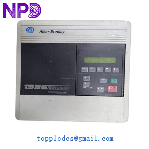
- Model: 1336F-BRF50-AA-EN-HAS2
- Brand: Allen Bradley (Rockwell Automation)
- Series: 1336 PLUS II Adjustable Frequency AC Drive
- Core Function: Precise speed control for induction motors in industrial automation
- Condition: New Surplus (Genuine original, never used, non-refurbished)
- Type: Variable Frequency Drive (VFD)
- Key Specs: 5 HP (3.7 kW) | 380-480 V AC | IP20 (NEMA 1) Enclosure
- Input Voltage Range: 380-480 V AC, 3-Phase, 50/60 Hz
- Output Power: 5 HP (3.7 kW)
- Output Current: 8.5 A
- Enclosure Rating: IP20 / NEMA Type 1
- Control Logic: Sensorless Vector Control for high torque at low speeds
- Interface: HAS2 (Human Interface Module: Programmer/Display with Digital Pot)
- Language: EN (English)
- Frame Size: B Frame
- Operating Temperature: 0 to 40°C (32 to 104°F)
- Communication Capability: Compatible with SCANport modules (DeviceNet, ControlNet)
Installation & Configuration Guide
Phase 1: Pre-Installation (15 Minutes)
⚠️ Safety Protocol:
- Lock out/Tag out (LOTO) all primary power sources.
- Crucial: After disconnecting power, wait at least 5 minutes for the DC bus capacitors to discharge. Use a multimeter to verify voltage at terminals +DC and -DC is near 0 V.
- Wear a grounded ESD wrist strap when handling the internal control boards.
Backup Checklist:
- Note the parameters from the old drive if it is still partially functional.
- Take high-resolution photos of the power terminal wiring (L1, L2, L3) and motor leads (U, V, W).
- Document the control wire positions on the TB3 terminal block.
Phase 2: Removal & Mechanical Mounting (20 Minutes)
- Loosen the conduit connections and clear the wiring from the drive base.
- Remove the mounting screws from the four corners of the B-frame chassis.
- Inspect the mounting surface; ensure the new 1336F-BRF50 has at least 4 inches (102 mm) of clearance above and below for proper airflow.
Phase 3: Wiring & Configuration (30 Minutes)
- Power Connection: Connect input leads to R, S, and T. Connect motor leads to U, V, and W. Ensure the ground lug is securely fastened to the sub-panel.
- Control Wiring: Replicate the TB3 connections. If using the HAS2 module for local control, ensure the jumper settings for “Local/Remote” match your previous setup.
- Parameter Entry:
- On power-up, use the HAS2 keypad to enter the Motor Nameplate Data (Voltage, Amps, RPM).
- Set Parameter 05 (Maximum Voltage) and Parameter 06 (Maximum Frequency).
- Verify the Stop Mode (Coast vs. Ramp) to match your application’s safety requirements.
Phase 4: Commissioning & Test (20 Minutes)
- Initial Power-Up: Check the display for “Ready” status. If an “F4” (Under Voltage) or “F5” (Over Voltage) fault appears, verify your line supply.
- Direction Test: Bump the motor at a low frequency (5 Hz) to verify the correct rotation. Swap any two motor leads if direction is reversed.
- Load Test: Gradually increase frequency to the operating setpoint while monitoring motor current on the HAS2 display.
Customer Cases & Industry Applications
Case 1: Food Processing Facility Emergency Recovery A large-scale bakery in the Midwest experienced a failure on a critical conveyor drive (a legacy 1336 PLUS II). The original drive’s control board failed due to flour dust ingress over 12 years. Since the plant’s entire SCADA logic was built around this specific model’s I/O mapping, upgrading to a PowerFlex series would have required 48 hours of PLC code rewriting. We shipped a 1336F-BRF50-AA-EN-HAS2 via next-day air. The maintenance team swapped the unit and entered parameters in under 2 hours, saving the facility an estimated $40,000 in wasted dough and lost production time.
Case 2: Strategic Buffer Stock for HVAC OEM A system integrator managing a municipal water treatment plant realized that their aging chemical dosing pumps relied on 1336F series drives, which are now obsolete. Rather than waiting for a catastrophic failure that would trigger environmental fines, they purchased our remaining “New Surplus” units as buffer stock. Six months later, a lightning strike took out two drives. Because they had the spares on-site, they achieved a “Zero Downtime” repair. They spent 5,000 on spares to avoid a potential 100,000 emergency system overhaul.
Frequently Asked Questions (FAQ)
Q: This model is discontinued. Is this a used or “pulled” unit? A: Absolutely not. This is New Surplus. In my experience, “pulled” drives often have dried-out electrolytic capacitors that fail within weeks. This unit has been kept in a climate-controlled environment and shows zero signs of terminal wear or mounting marks. It’s a clean, original Allen Bradley factory build.
Q: Can I replace a 1336S series with this 1336F series? A: Yes, generally. The 1336F (PLUS II) is the successor to the 1336S (PLUS). They share similar physical dimensions and the same parameter structure. However, always double-check your communication adapter (like a 1203-GK5) to ensure it seats properly in the new frame.
Q: What does the “HAS2” suffix specifically provide? A: The HAS2 is the high-end Human Interface Module. It includes a multi-line LCD for easy programming and, importantly, a digital potentiometer for manual speed adjustment. If your operator relies on a physical knob to tweak speed, this is the exact version you need.
Q: Does the drive come with a manual? A: While we include the original factory documentation when available, these older units sometimes have weathered paper. We provide a digital PDF copy of the 1336 PLUS II User Manual with every purchase to ensure your technicians have the full parameter map at their fingertips.
Q: How do you test a VFD that has been in storage for a long time? A: We perform a Capacitor Reforming procedure if the unit has been shelved for over 2 years. We apply a gradual voltage to the DC bus using a variable AC source to safely “wake up” the chemical layers in the capacitors. We then run the drive under a 5 HP load for 24 hours before it leaves our facility. We can provide the test log and a video of the motor running upon request.