
Description
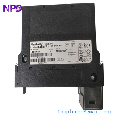
- Model: 1756-IF16A
- Brand: Allen-Bradley (Rockwell Automation)
- Series: ControlLogix (1756)
- Core Function: 16-Channel Non-Isolated Analog Input Module
- Product Type: Analog I/O Module
- Key Specs: 16 Single-ended or 8 Differential Inputs 0–20mA / ±10V 16-bit Resolution
- Inputs: 16 Single-ended, 8 Differential, or 2 High-speed Differential
- Input Ranges: ±10.25V, 0–10.25V, 0–5.125V, 0–20.6mA
- Resolution: 16 bits (approx. 320 μV/count or 0.32 μA/count)
- Conversion Method: Sigma-Delta
- Backplane Current: 150mA @ 5.1V DC; 40mA @ 24V DC
- Power Dissipation: 2.3 W (Max)
- Module Scan Time: 12ms to 488ms (Dependent on filter settings)
- Removable Terminal Block (RTB): 1756-TBNH or 1756-TBSH (Not included)
- Calibration: Factory calibrated; supports user-initiated calibration
A-B 1756-IF16A
Application Scenarios & Pain Points
The 1756-IF16A is the high-density “bread and butter” analog card for the ControlLogix platform. Because it is non-isolated, all 16 channels share a common ground. This makes it a cost-effective choice for large-scale sensor integration where signals originate from the same power source or within the same cabinet. However, if your field sensors are powered by different loops, you may encounter ground loops that skew your data—a common headache for instrumentation techs.
Typical Application Scenarios:
- Process Monitoring Aggregating temperature, pressure, and flow transmitters in large water treatment or chemical processing plants.
- HVAC Control Monitoring multiple air quality and humidity sensors across a centralized facility.
- Oil & Gas Data Acquisition Collecting data from remote wellhead sensors where high channel density is required to save rack space.
- Energy Management Interfacing with power meters and current transducers to monitor real-time plant load.
Case Study: The “Common Ground” Conflict
Background: A brewery was using a 1756-IF16A to monitor 12 different level sensors on fermentation tanks. Suddenly, all readings began to drift whenever a specific pump motor started.
The Problem: Because the 1756-IF16A is non-isolated, the noise from the motor’s VFD was bleeding back through the common ground of the sensor loop. The drifting wasn’t a sensor failure, but a classic ground loop interference affecting the shared reference point of the module.
The Solution: We provided a replacement 1756-IF16A to rule out hardware fatigue. During installation, the team also added signal isolators between the noisy sensors and the PLC rack to “break” the shared ground.
Result: The readings stabilized immediately. The 1756-IF16A continued to provide high-resolution data without being affected by industrial noise.
A-B 1756-IF16A
Similar Product Recommendations
If your environment has high electrical noise or diverse power sources, you might need an isolated version of this module.
| Model Number | Compatibility | Main Difference | Integration Note |
| 1756-IF16 | ✅ Direct | Older Hardware Revision | Firmware may differ; check your Studio 5000 version. |
| 1756-IF8I | ⚠️ Isolated | 8 Channels, Fully Isolated | Use if you have ground loop issues between sensors. |
| 1756-IF16H | ⚠️ HART | 16 Channels with HART | Supports HART protocol for smart instrument diagnostics. |
Troubleshooting Quick Reference
| Symptom | Possible Cause | Relevance | Action |
| OK LED (Off) | No Power / HW Failure | ✅ High | Check if the module is fully seated in the rack. Check backplane 5V. |
| I/O LED (Blinking Red) | Configuration Mismatch | ✅ High | Check Studio 5000 I/O tree for “Module Fault.” Match the Rev number. |
| All Channels @ Max Value | Open Loop / Lost Ground | ⚠️ Medium | Check for a broken common wire or a blown fuse in the 24V loop. |
| Noisy Readings | EMI / Ground Loops | ⚠️ Medium | Ensure shielded cable is used and grounded at one end only. |
Technical SOP & Quality Guarantee
Analog modules require precision calibration to ensure the data you see on the HMI matches the physical world:
- Current Loop Accuracy Test: We inject 4.000mA and 20.000mA signals into every channel and verify the PLC registers values within 0.1% tolerance.
- Differential Stability Test: We check the “common mode rejection” to ensure the module correctly filters out noise between the positive and negative terminals.
- Burn-in Test: The module is run at 50°C for 24 hours to ensure the internal analog-to-digital (A/D) converters don’t drift as they heat up.
- Pin Continuity: We inspect the backplane pins and RTB connection points for any signs of oxidation or wear.
Engineer’s Pro-Tip: When configuring the 1756-IF16A, pay close attention to the “Real Time Sample” (RTS) interval. If you set it too fast for 16 channels, you can swamp the backplane with traffic. For most temperature or level loops, a 100ms sample rate is more than sufficient.