
Description
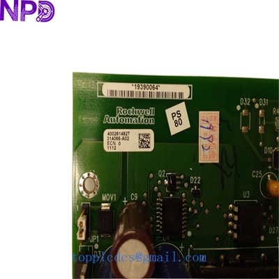
- Model: 314066-A02 (Cross-ref: 4002614827 / 4002577426)
- Brand: Allen-Bradley (Rockwell Automation)
- Series: PowerFlex / Large Drive Series Spare Parts
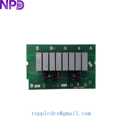
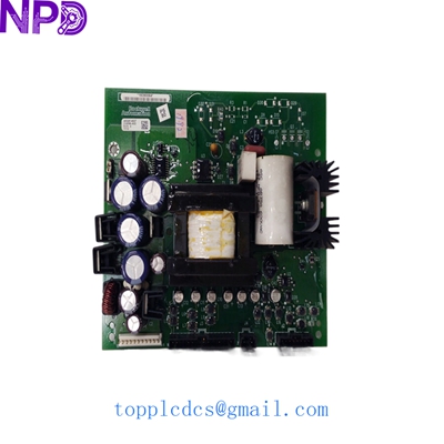
- Core Function: Gate Driver / Power Interface Control Board
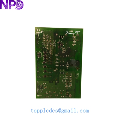
- Product Type: Printed Circuit Board Assembly (PCBA)
- Key Specs: Multi-layer logic | High-voltage isolation | Gate trigger circuitry
- Nominal Voltage: System-dependent (typically 460V – 600V AC drive systems)
- Component ID: 4002614827 (Main PCB ID)
- Sub-Assembly ID: 4002577426
- Application: Used in high-horsepower AC/DC Variable Frequency Drives (VFD)
- Isolation: Opto-isolated gate signals for power semiconductor protection
- Connector Type: Ribbon cable headers and high-current screw terminals
- Coating: Heavy industrial conformal coating (protects against conductive dust)
- Diagnostic Features: On-board LED status for gate pulse verification
- Manufacturing Standard: UL, CE compliant
- Revision: -A02 (Optimized thermal management revision)
ALLEN BRADLEY 314066-A02 40026148274002577426
Installation & Configuration Guide
Stage 1: Pre-Installation
⚠️ Safety Warning:
- Lethal Voltage: This board controls power semiconductors (IGBTs/SCRs). Ensure the drive is locked out and tagged out (LOTO).
- Capacitor Bleed: VFD DC buses can hold 600V+ for over 15 minutes after power-off. Measure the DC bus with a 1,000V rated meter before touching anything.
- Static Sensitivity: The gate driver chips are extremely fragile. Use a grounded ESD mat and wrist strap.
Required Tools:
- M4/M5 Metric socket set (for terminal connections)
- Torque wrench (accurate to 2.5 N·m)
- High-voltage insulation tester (Megger)
Stage 2: Removal
Steps:
- Map the Wiring: Take photos of the gate leads (usually twisted pair wires). Getting these out of phase will result in a catastrophic “Shoot-Through” failure.
- Disconnect Leads: Carefully unplug the ribbon cables. If they are brittle from heat, use a small pick to release the locking tabs.
- Unmount: Remove the plastic standoffs. Inspect the thermal pads behind the board; if they are torn, they must be replaced.
Stage 3: Installation
Steps:
- Verification: Compare the 314066-A02 number with your failed unit. Ensure the “A02” suffix matches; earlier revisions may have different timing constants.
- Seating: Align the board over the IGBT modules. Ensure the pin headers are perfectly straight before applying pressure.
- Torque Specs: When reconnecting power terminals, use a torque wrench. Under-tightening causes arcing; over-tightening cracks the PCB.
Stage 4: Power-On & Testing
Validation:
- Static Test: With main power OFF and control power ON, verify the diagnostic LEDs on the board are green.
- Gating Test: If your drive supports “Open Loop” testing, verify gate pulses without high voltage applied to the bus.
- Full Load: Gradually increase the motor load. Listen for “hunting” or uneven harmonics, which could indicate a misaligned gate signal.
ALLEN BRADLEY 314066-A02 40026148274002577426
Customer Cases & Industry Applications
Case 1: Mining Conveyor Drive Emergency Restore
Situation: A gold mine in Australia had a 500HP Allen-Bradley drive fail on their primary conveyor. The diagnostic pointed to a gate driver board failure (314066-A02).
Task: The mine was losing $120,000 in throughput per day. Rockwell lead times for this legacy part were “Indefinite.”
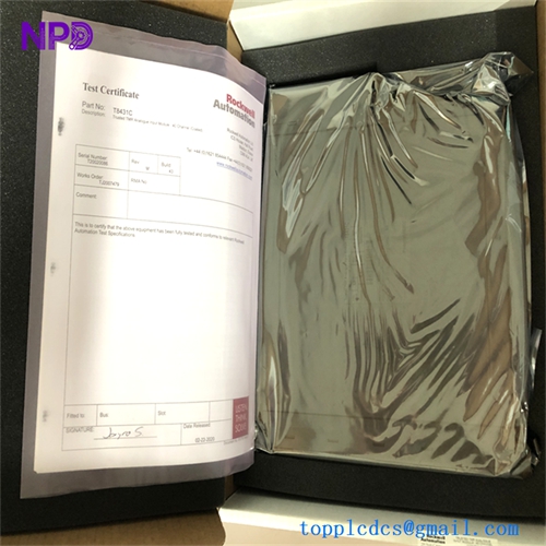
Action: We supplied one unit of 4002614827 New Surplus. We provided the customer with the original factory test report from our QC lab.
Result: The board was installed within 48 hours. The mine resumed full production, and the maintenance lead commented that the “A02” revision actually ran cooler than their original “A01” version.
Case 2: Water Treatment Pump Station Spare Strategy
Situation: A municipal water utility used several aging PowerFlex drives for high-pressure pumps. They realized that a single board failure could leave a district without water.
Task: They needed a specific set of critical spares that were no longer actively manufactured.
Action: We sourced two matching 314066-A02 boards. Since these are “New Surplus,” they have the full lifespan of a new part, unlike “Refurbished” boards that may have stressed capacitors.
Result: The utility now has a “Zero-Day” recovery plan. They avoided the multimillion-dollar cost of upgrading three entire drive cabinets by simply stocking $5,000 in strategic PCBs.
Frequently Asked Questions (FAQ)
Q: Why are there multiple numbers (314066-A02, 4002614827) on the board? A: This is common with Allen-Bradley power components. The 314066 is often the assembly number for the complete module, while 400261… refers to the raw PCB or the specific circuit design. We verify all these numbers to ensure 100% compatibility.
Q: Does this board include the thermal interface material? A: Our New Surplus stock typically includes the original factory-applied thermal backing. If yours is missing, we recommend using a high-quality non-conductive thermal paste during installation.
Q: Is “A02” compatible with “A01”? A: In most cases, yes. The “A02” is a functional upgrade that usually addresses heat dissipation or noise immunity. However, in my experience, if you are running a redundant or parallel drive, it is best to have matching revisions on both sides.
Q: How do I know this isn’t a “pulled” or “used” part? A: We inspect the mounting holes. A “used” board will have visible “bite marks” from the screws in the gold or tin plating. Our New Surplus boards have pristine, un-marked mounting points and ship in sealed anti-static bags.
Featured Inventory List (Current Stock)
- ABB 3BSE018161R1 (PM866)
- Bently Nevada 3500/22M
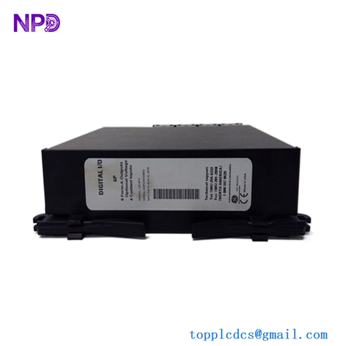
- Triconex 3503E Digital Input
- GE IS215UCVEH2AE
- Honeywell CC-PAIH01
- Siemens 6ES7 414-2XG03-0AB0
- Allen-Bradley 1756-L73
- Schneider 140CPU65150
For more details on these parts, visit our catalog at newplcdcs.