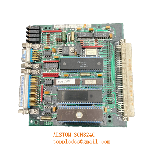
Description
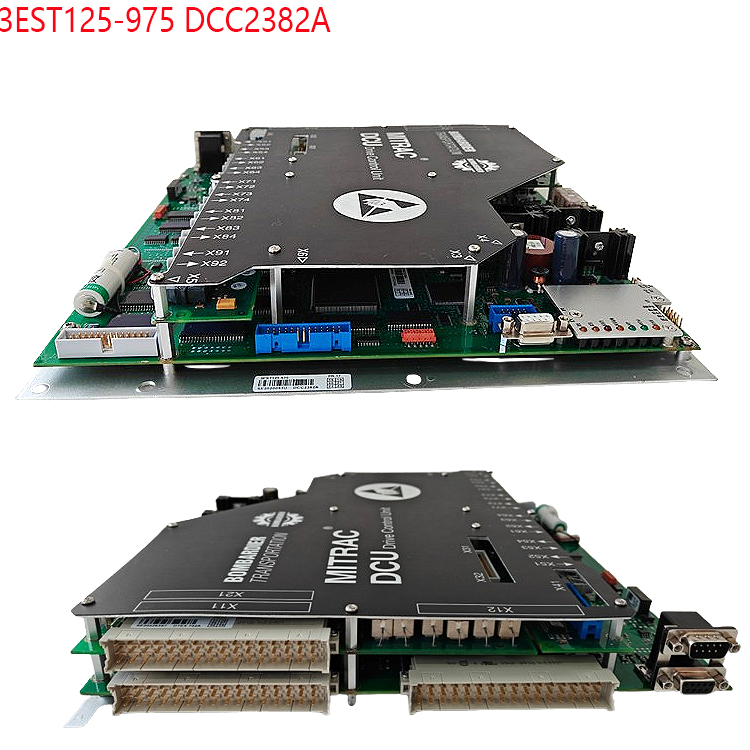
- Model: 3EST125-975
- Brand: ALSTOM (France)
- Series: Industrial Drive & Power Conversion Series
- Core Function: Centralized drive control and firing logic for power converters.
- Condition: Brand New Surplus (Original, non-refurbished)
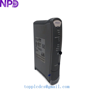
- Type: Drive Control Unit / Processor Board
- Key Specs: 24 V DC Logic Power, Pulse Transformer Interface, Diagnostic LEDs
- Module Type: Digital Drive Controller
- Control Voltage: 24 V DC (±15%)
- Input Channels: Analog and Digital feedback (Encoder/Tachometer inputs)
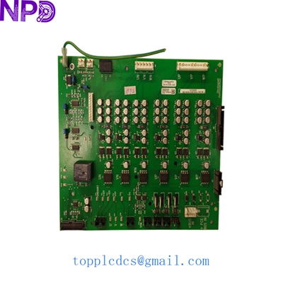
- Output Type: PWM Gate Drive signals for thyristors/IGBTs
- Communication: Proprietary Serial Link / Parallel Bus Interface
- Cooling: Passive (Heatsink integrated if applicable)
- Operating Temp: -5°C to +60°C
- Protection: Conformal coating for humidity and dust resistance
- Isolation: Opto-isolated I/O for high-voltage noise immunity
3EST125-975
Installation & Configuration Guide
Phase 1: Pre-Installation (Preparation: 15 minutes)
⚠️ Safety First:
- Drive control units deal with high-power circuits. Ensure the main AC/DC supply is locked out and tagged out (LOTO).
- Use a voltmeter to verify that the DC link voltage has dissipated to below 50 V.
- Keep the unit in its anti-static bag until the moment of installation.
Tools Needed:
- Fine-tip torque screwdriver (for ribbon cable connectors)
- Anti-static wrist strap (ESSENTIAL for this specific board)
- Digital Multimeter (Fluke 115 or similar)
Phase 2: Removing the Faulty 3EST125-975
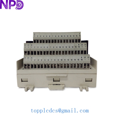
- Mark Cables: Before disconnecting, use a fine-tip marker to label every ribbon cable and terminal wire.
- Terminal Disconnection: Carefully unscrew the power and signal leads.
- Pulling the Board: If the board is part of a rack system, loosen the thumb screws and slide it out horizontally. Avoid touching any exposed solder points on the back.
- Inspect the Rack: Check the backplane connector for any signs of arcing or burnt pins before sliding in the new unit.
Phase 3: Configuration & Power-Up
- Hardware Matching: Compare the jumper settings (JP1, JP2, etc.) on the new 3EST125-975 with the old board. These often define the drive address or motor type.
- Installation: Slide the new module into the slot. Ensure it “seats” firmly into the backplane connector.
- Software/Firmware:
- Note: These Alstom boards may contain EPROMs or Flash memory. In my experience, if the firmware version on the new board is different from the old one, you may need to swap the EPROM chips from the original board to the new one to retain custom motor parameters.
- Test Run: Power up the control circuit only (no high voltage). Check the status LEDs. A “Ready” or “Run” green light indicates the board has passed its internal self-test.
Customer Cases & Industry Applications
Case 1: Steel Mill Rolling Line Downtime
Situation: A major steel mill in Eastern Europe used ALSTOM 3EST125-975 units to control the main DC motors on their rolling stands. One stand failed due to a control board fault, halting the entire line.
Task: The mill was losing approximately $15,000 per hour. The original equipment manufacturer (OEM) had declared the part obsolete with no immediate replacement.
Action: We identified a 3EST125-975 in our “New Surplus” inventory. We performed a bench test of the gate drive pulses and shipped the unit via international priority.
Result: The mill was back in production within 72 hours of the failure. The maintenance lead noted that the “New Surplus” quality ensured they didn’t have to worry about the component aging issues often found in refurbished “pulls” from other sites.
Case 2: Marine Propulsion System Maintenance
Situation: A research vessel equipped with Alstom propulsion drives reported “Gate Drive Faults” on the starboard drive during sea trials.
Task: The vessel could not proceed with its mission until the drive was reliable. Space was limited, and the crew needed a direct “Plug-and-Play” replacement.
Action: We provided a verified New Surplus board. We also included a detailed “Installation Checklist” (similar to the one above) to assist the shipboard engineers.
Result: The swap was completed while at port. The vessel successfully completed its sea trials without further alarm incidents. The engineer noted, “Finding this specific Alstom part saved us from a million-dollar system retrofit.”
Frequently Asked Questions (FAQ)
Q: Is the 3EST125-975 compatible with all Alstom drives? A: No. This board is specific to certain series of Alstom power converters. You must match the 3EST125-975 part number exactly. If your board has a different suffix (e.g., -976), contact us to check for compatibility.
Q: Does this board include the software/parameters? A: The board contains the operating firmware, but the “application-specific” parameters (like motor current limits) are usually stored in a removable EPROM or on the main system controller. We recommend swapping the EPROM from your old board if you want to keep your specific settings.
Q: Can I repair my old board instead? A: Drive control boards are highly complex. While some components can be replaced, the multi-layer PCB and proprietary Alstom ICs make reliable repairs very difficult. A New Surplus unit is always a safer investment for critical production lines.
Q: What is the warranty on “Surplus” parts? A: We provide a full 12-month warranty. If the module fails under normal operating conditions, we will replace it or offer a full refund.
Current Inventory Specials
In addition to the ALSTOM 3EST125-975, we stock several critical drive and DCS parts:
- ABB PP836A 3BSE042237R2
- GE SBI-PDP-32
- ICS Triplex T9110
- ABB UCD224A103 3BHE023681R0103
- Honeywell TC-RPCX01
- Bently Nevada 3500/15
- Siemens 6ES7315-2AH14-0AB0
- Schneider 140CPU65160
Check our full stock at www.newplcdcs.com.