
Description
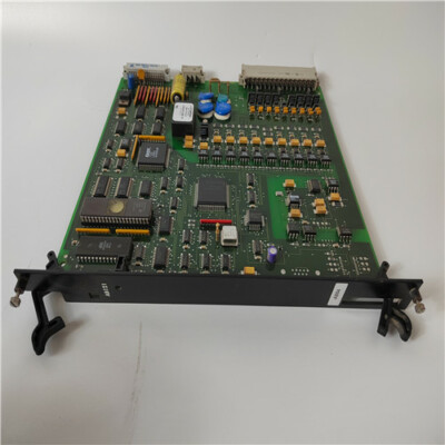
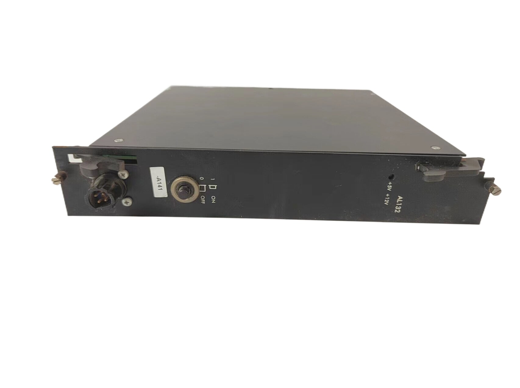
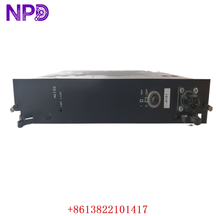
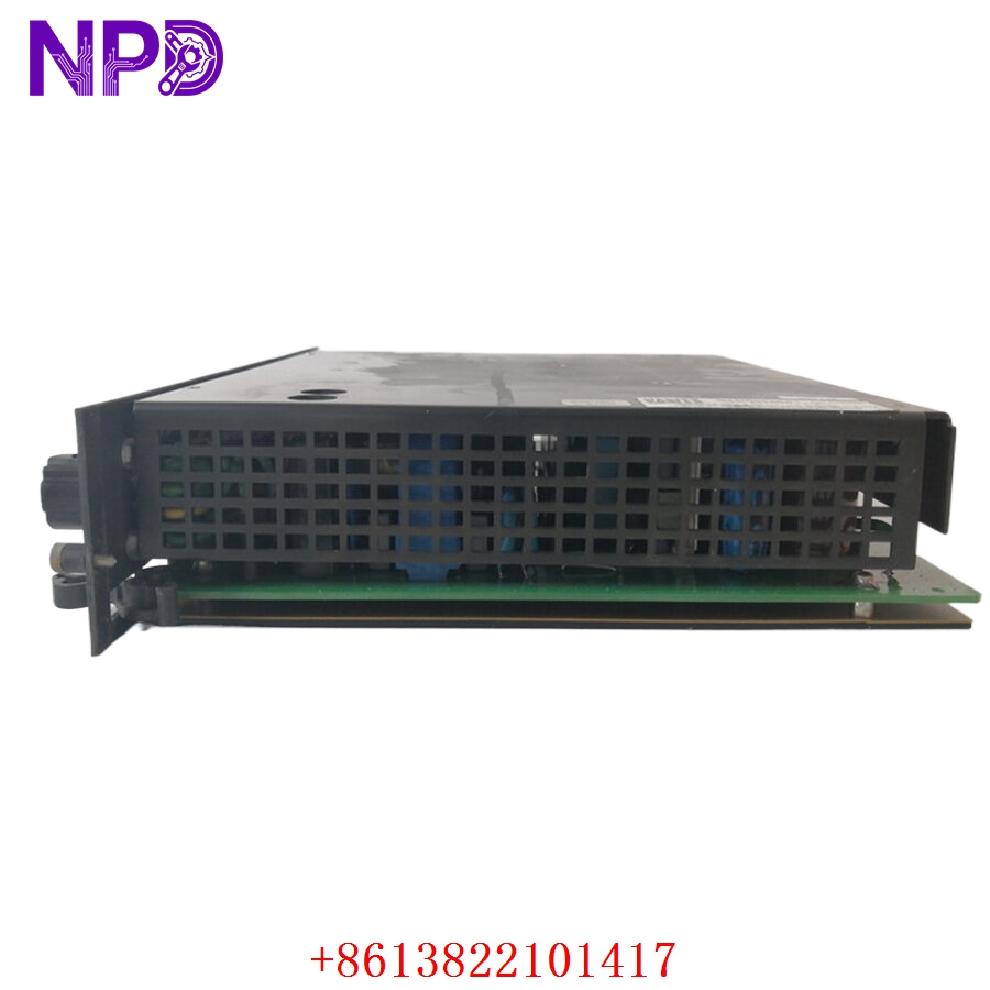
- Model: Alstom AL132 / AL132A (Component Blueprint ID: STO0982E01)
- Brand: Alstom / GE Grid Solutions (France)
- Series: Alstom Industrial Control & Protection Series (Widely utilized in gas/steam turbine governor systems, power plant substation automation, and legacy distribution control grids)
- Core Function: Serves as the central processing hub for synchronous automation sequences, real-time data computational algorithms, and communication interface management, Brand New Surplus condition
- Type: Main Processing / Controller Board
- Key Specs: 32-Bit industrial architecture | High-density onboard non-volatile memory | Multi-protocol communication bus interface
- Processor System: High-reliability 32-bit embedded industrial RISC core
- Memory Subsystem: High-speed volatile RAM alongside onboard non-volatile EEPROM/Flash for application firmware retention
- Communication Pipelines: Dedicated serial links (RS-232/RS-485 arrays) and high-speed local network bus interfaces
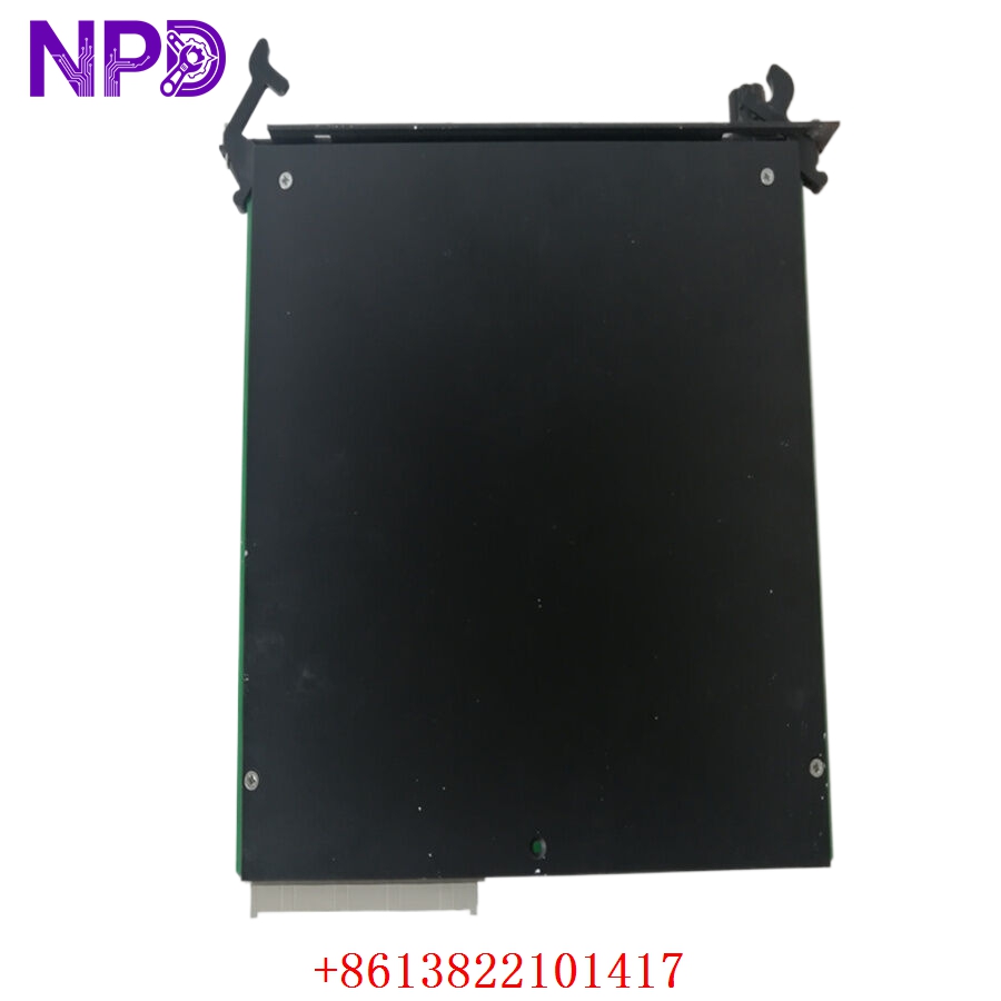
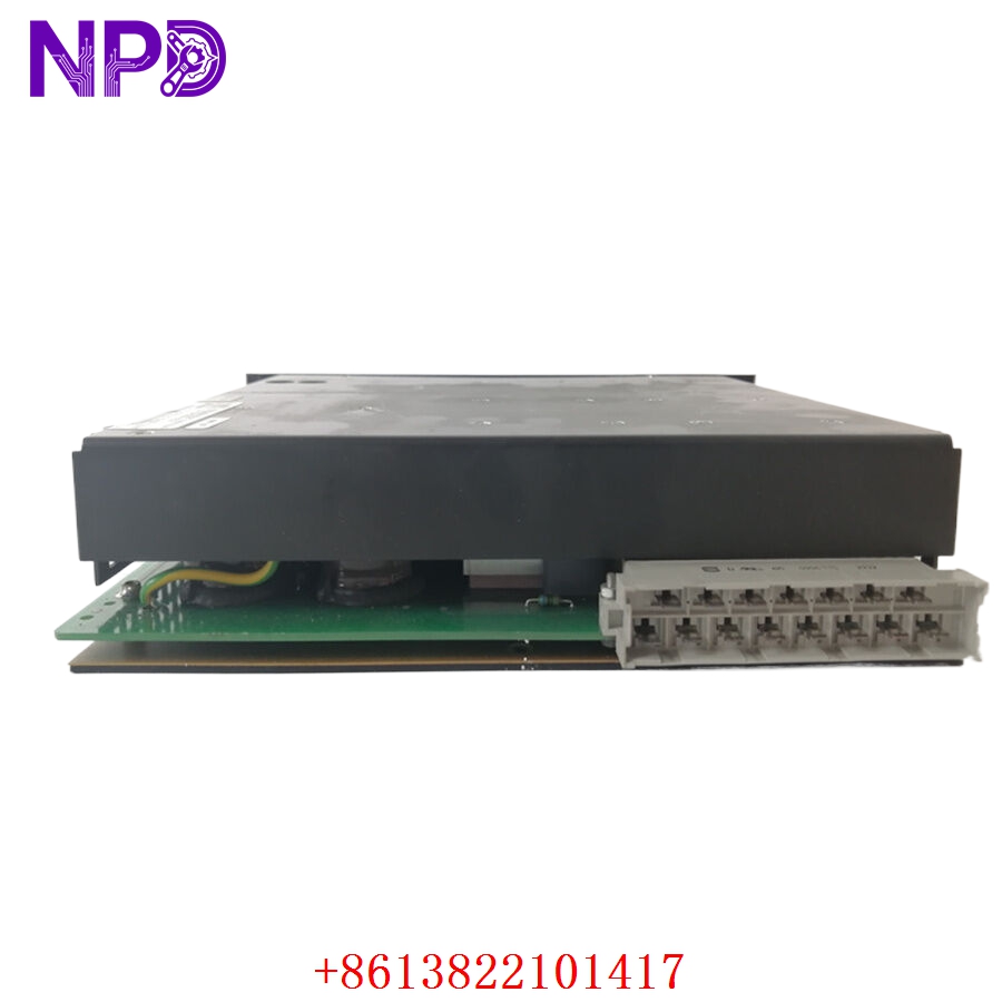
- Backplane Form Factor: Parallel multi-pin eurocard connector block matching Alstom industrial sub-rack configurations
- Galvanic Isolation: Minimum 1,500 V DC isolation barrier safeguarding internal logic from external loop noise
- Diagnostic Panel Layout: Front-plate multi-segment status LEDs (Run, System Fault, Memory Error, Comm Link Active)
- Power Draw Requirements: +5 V DC and \pm12 V DC drawn directly via the sub-rack backplane network
- Climatic Tolerance Limits: -10 °C to +60 °C (Within clean-air, non-condensing industrial panels)
ALSTOM AL132 AL132A STO0982E01
ALSTOM AL132 AL132A STO0982E01
Part 4: Installation & Configuration Guide
Phase 1: Pre-Installation (Estimated Time: 20 minutes)
⚠️ Safety First:
- Coordinate with your station operations room to isolate the relevant turbine, line, or processing cell. Never pull a main processing controller card while the connected equipment is operating automatically.
- Shut off the primary auxiliary power breakers feeding the target control rack cabinet.
- Apply standard Lockout/Tagout (LOTO) padlocks and warning tags to the power source breaker switch.
- Wait a minimum of 5 minutes for the sub-rack power supply capacitors to discharge safely to 0 V before moving or handling components.
Tool Preparation:
- Static-dissipative grounding wrist strap connected to a verified chassis ground
- Clean, static-safe ESD workspace handling mat
- Slotted precision instrument screwdriver (2.0 mm blade)
- Phillips screwdriver for faceplate screws
- Fluke 115 Digital Multimeter
- Wire marker tags and a high-resolution smartphone camera
Backup Procedures:
- CRITICAL: Connect your engineering terminal laptop to the programming port on the existing board. Download and export a full operational backup of the active application program files, parameters, and baseline firmware variables. Store a copy in your master plant configuration folder. Sourcing an un-used surplus card means you are installing a blank slate that requires this localized profile.
Phase 2: Removal (Estimated Time: 10 minutes)
Steps:
- Confirm using your multimeter that all front panel communications ports and terminal inputs read 0 V AC/DC.
- Label each front-facing communication plug and data cable with your wire markers, then carefully unplug them.
- Back out the upper and lower captive mounting screws anchoring the AL132 / AL132A faceplate to the rack rails.
- Grasp the extraction handles firmly and pull them outward evenly to slide the card out of its parallel backplane interface socket pins.
- Guide the module straight out along its guide tracks and place it immediately into an ESD shielding bag.
⚠️ Key Notes:
- Inspect the old board for any physical revisions, specialized jumper wires, or field-installed component changes that might need to be replicated on your replacement module.
Phase 3: Installation (Estimated Time: 20 minutes)
Steps:
- ESD Protection: Secure your anti-static wrist strap before opening the sealed antistatic wrap containing the new surplus STO0982E01 card.
- Jumper and Dip Switch Replication: Look closely at the raw circuit board layer of the new card. You must check all physical hardware jumpers, DIP switches, or rotary selectors and set them to match your decommissioned card exactly. These govern hardware slot addressing, node IDs, and logic scaling configurations.
- Insert Card: Align the upper and lower edges of the processor circuit board within the designated card guide tracking lanes of the rack slot.
- Seat Connectors: Slide the card smoothly inward until it contacts the backplane. Press firmly until the rear multi-pin connector seats completely into the backplane socket assembly.
- Secure Panel: Tighten the top and bottom faceplate screws to lock the card to the rack frame, then re-attach your serial communication lines.
Self-Check Checklist:
- [ ] Onboard hardware jumper layouts and DIP switch configurations match the legacy card exactly
- [ ] Multi-pin backplane connectors are fully engaged with zero mechanical play
- [ ] Faceplate mounting screws are hand-tightened down flush with the rack rails
- [ ] No loose tools, stray hardware, or wire clippings are left inside the sub-rack space
Phase 4: Power-On & Programming Loading (Estimated Time: 25 minutes)
Pre-Power Checks:
- Check for any low-resistance shorts to ground across the sub-rack power lines using your multimeter. Verify that the auxiliary rack voltages match standard factory specifications.
Power-On Steps:
- Turn on the primary sub-rack power distribution breaker to energize the system.
- Observe Initial LED Status: The front panel FAULT or CONFIG lights may illuminate initially while the processor runs its startup diagnostics on an empty memory blank. This is expected.
- Connect your engineering terminal laptop to the programming interface port.
- Open your saved plant system project and upload/restore the master system parameters and runtime control logic files to the new processor board.
- System Verification: Execute a warm restart or cold initialization command via the software interface as required by your architecture guidelines. The green RUN or OK light should turn solid, and all red fault lights must clear.
- Verify that communication with neighboring I/O modules and downstream DCS nodes is fully active. Observe the unit under low-load conditions for 15 minutes before re-engaging active safety loops. Record the new serial number in the plant maintenance log.
Part 5: Customer Cases & Industry Applications
Case 1: Restoring Turbine Governor Control at an Industrial Cogeneration Plant
Situation:
An industrial cogeneration facility uses an Alstom control rack system to manage a steam turbine governor loop. During a hot-weather peak run, a logic processing fault locked up the main processor module, part number AL132 (STO0982E01), dropping communication with downstream actuator drives and causing an immediate automated turbine trip.
Task:
The plant lost its steam generation synchronization line, running up significant idle capacity penalty fees for every hour the governor control panel sat dark. Because Alstom had moved this product platform into obsolete status, standard distribution networks quoted an 8 to 12-week factory lead time to track down or rebuild a replacement card from secondary global depots.
Action:
The plant’s automation engineering lead reached out to our logistics hub. We located a pristine, un-used surplus AL132A STO0982E01 processing card in our sterile inventory. Our laboratory staff initialized the board on our test chassis, updated it to the proper base firmware revision, and verified both the front serial ports and rear data pipelines before dispatching it via priority overnight air courier.
Result:
- Outage Terminated: The package reached the plant site within 14 hours of the initial fault. The maintenance technicians matched the DIP address mappings and mounted the board before noon.
- Full Recovery: The engineering team re-loaded the site configuration file without issue. The board synchronized perfectly on power-up, restoring stable governor control and enabling the generator to safely re-connect to the power grid.
- Customer Voice: “Sourcing an un-used, factory-clean processor module for an older Alstom rack on short notice seemed nearly impossible. Getting it from your stock with verified testing data saved our plant timeline and resolved a major critical incident.”
Case 2: Strategic Spares Allocation for an Industrial Substations Utility
Situation:
A heavy manufacturing facility running an intensive electrochemical process relies on an older Alstom grid architecture to manage its main electrical substation. The protection cabinet relies on multiple legacy AL132 cards to handle real-time data computational algorithms and communications.
Task:
Knowing that a sudden controller failure would stall production—the plant’s reliability team wanted to secure a reliable, un-degraded backup processor before global market supplies dried up. Using refurbished or repaired pull-outs on this critical node was rejected due to safety and reliability concerns.
Action:
The procurement manager contacted us to locate authentic, un-used surplus components. We supplied a matching STO0982E01 module inside its original, sealed anti-static factory packaging, complete with clean manufacturing numbers, allowing the facility to confirm the pristine condition of the board before adding it to their safety stock.
Result:
- Long-Term Protection: This strategic purchase provided the plant with a reliable, plug-and-play backup component, ensuring they can keep their legacy control systems running smoothly for years to come without requiring an expensive and un-planned full-system upgrade.
Part 6: Frequently Asked Questions (FAQ)
Q1: What is the physical distinction between the AL132 and AL132A designations?
A: The AL132A represents a minor hardware revision and optimization update of the original AL132 motherboard design. Both iterations utilize the identical core blueprint code STO0982E01 and feature the exact same backplane multi-pin interface matrix.
The AL132A includes updated internal heat-dissipation pathways and optimized logic processing chips that run cooler under high-load cycles. The AL132A is completely backward-compatible and serves as a direct drop-in replacement for the standard AL132 slot position.
Q2: Why is it vital to copy the physical jumper arrays and DIP switches from our old board layout?
A: The STO0982E01 processor card is designed to function across multiple slots and network nodes within the Alstom sub-rack environment.
The onboard DIP switches and hardware jumpers govern vital configurations, including its unique communication address on the rack backplane, communication baud rates, and hardware allocation maps. Installing a replacement card without matching these settings can prevent the master processor network from finding the board or lead to communication fault alarms in the control room.
Q3: Can I hot-swap the AL132/AL132A card while the control sub-rack is powered and live?
A: No, you should never hot-swap a main system processor card while the rack power is active. Pulling a central processing board while the backplane data bus is energized can cause electrical arcing across the high-density connection pins.
This can corrupt data on adjacent communication lines, damage the internal processing chips, or cause connected safety and I/O modules to enter an unpredictable fault state. Always shut off auxiliary power to the rack chassis before pulling or installing a processor.
Q4: Why buy a New Surplus Alstom processor module instead of a cheaper refurbished option online?
A: Refurbished processor cards are typically salvaged from old, decommissioned industrial plants. Third-party repair shops often just clean the outer terminals or replace worn-out faceplate components, leaving old internal memory chips, processing chips, and capacitors intact. These old components are prone to failing unexpectedly when subjected to continuous data transmission.
Our New Surplus units are authentic, un-used modules stored in climate-controlled warehouses. They provide factory-original component lifespans and come backed by a full 12-month warranty, ensuring reliable protection for your machinery without the risks of refurbished hardware.
Q5: How do you verify the functionality of the processor before shipping?
A: Every AL132 / AL132A module goes through a rigorous quality check on our specialized testing benches before leaving our facility. We slide the card into a live matching sub-rack, connect an engineering terminal, and test the full memory range, processing cycles, and communication port speeds.