
Description
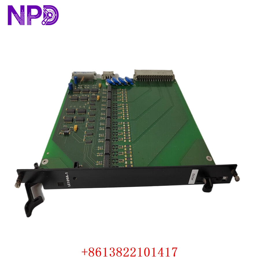
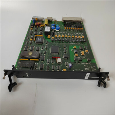
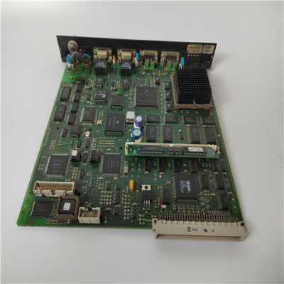
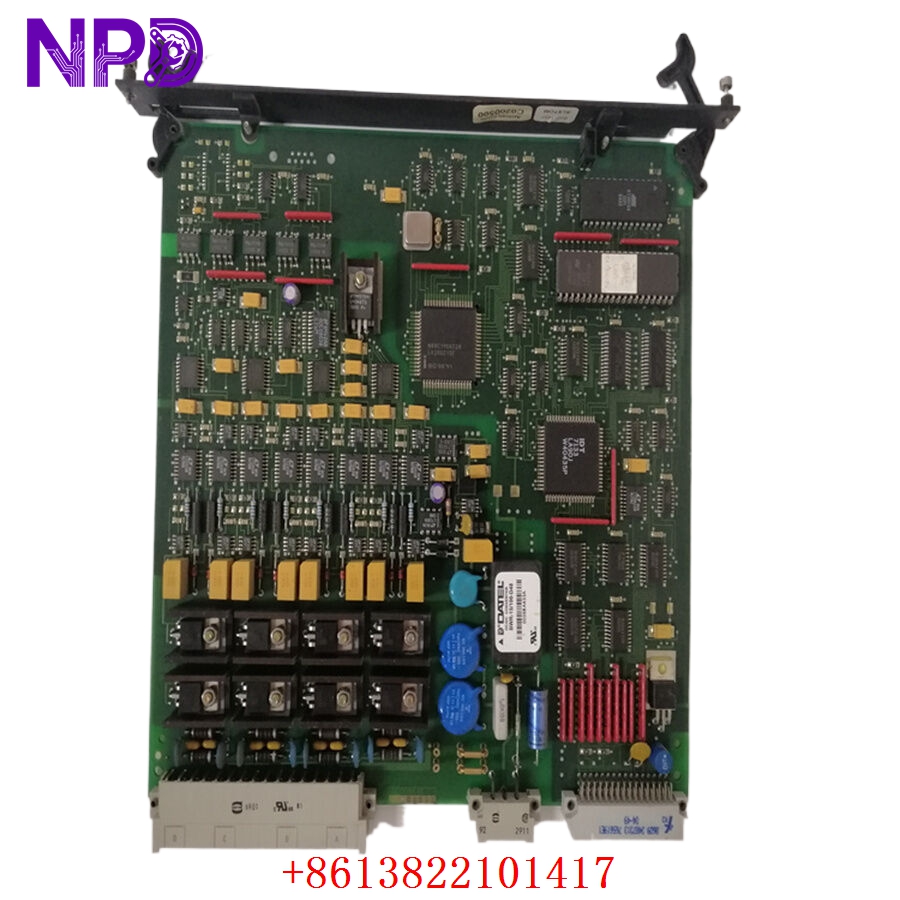
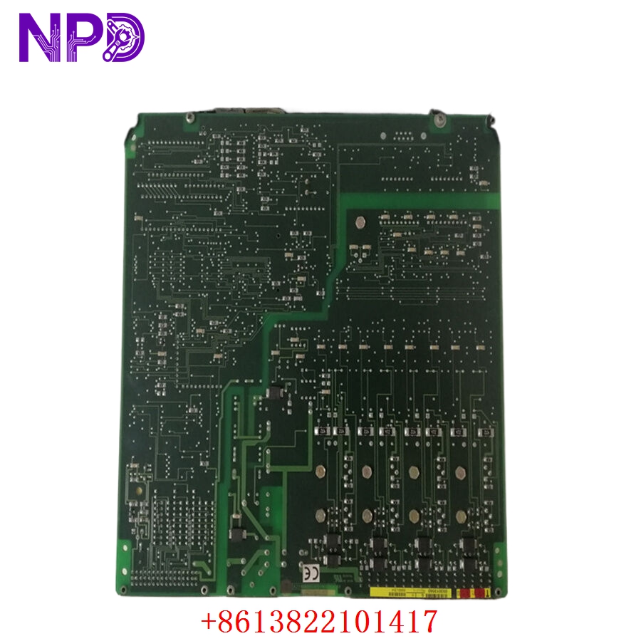
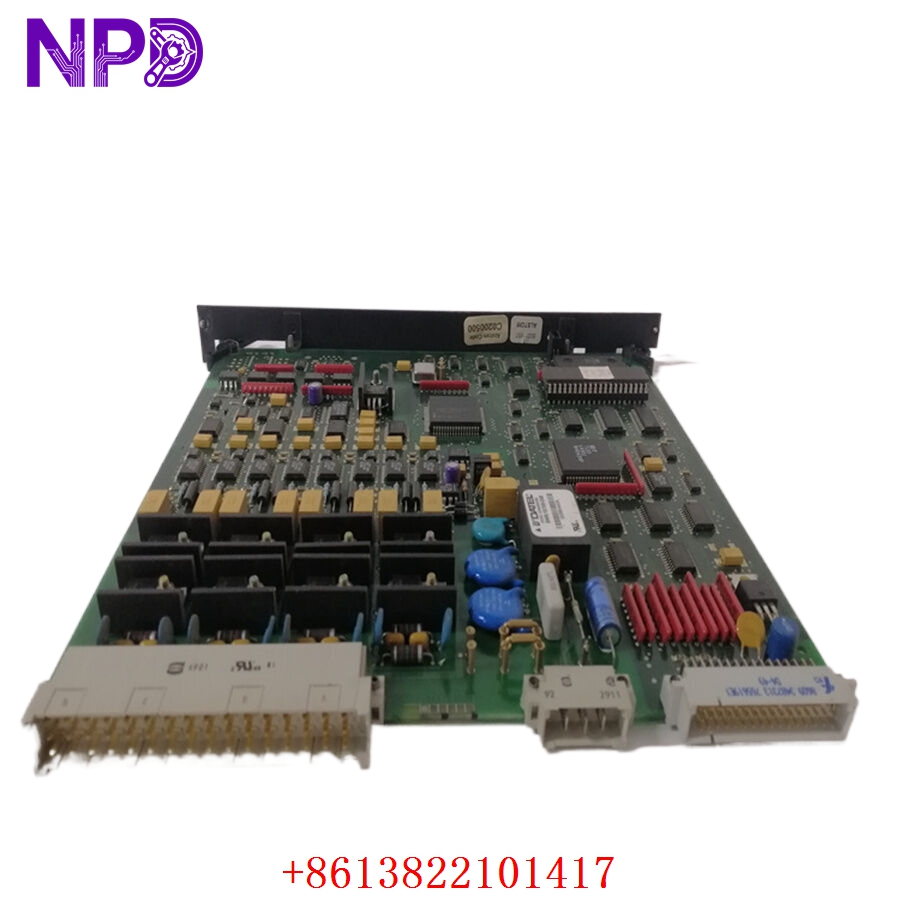
The ALSTOM AS111-1 is a high-performance analog output module designed for the ALSPA CE2000 and CE3000 Distributed Control System (DCS) architectures. Engineered primarily for high-reliability process regulation and turbine control systems (such as the ALSPA P320 platform), this module provides precise, multi-channel loop outputs to control field actuators, positioners, and variable speed drives. Featuring internal galvanic isolation between the digital processing core and the external process loop, the AS111-1 manages real-time current distribution and output readback diagnostics. This ensures safe system fallback execution and maximum fault tolerance within demanding power generation, thermal utility, and heavy chemical processing plants.
Product Specifications
- Model Number: AS111-1
- Manufacturer: ALSTOM (ALSPA Control Systems)
- Control System Series: ALSPA CE2000 / CE3000 / P320
- Function: Multi-Channel Analog Output Module
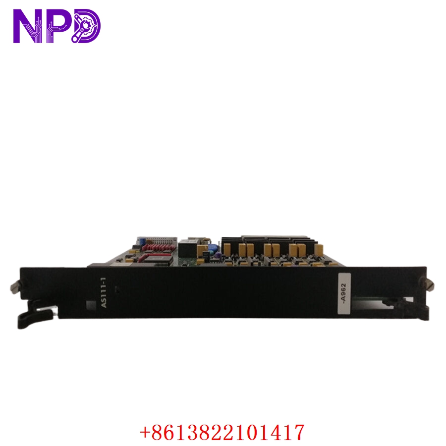
- Dimensions: 265 mm x 26 mm x 265 mm (Standard Eurocard rack profile)
- Weight: 0.51 kg (1.12 lbs)
- Country of Origin: France
- Number of Channels: 8 independent current channels
- Output Signal Ranges: 0 to 20 mA or 4 to 20 mA configurations
- Resolution and Accuracy: 16-bit binary conversion with 0.1% baseline accuracy
- Isolation Protection: Built-in optoelectronic galvanic isolation between system bus and field channels
ALSTOM AS111-1
ALSTOM AS111-1
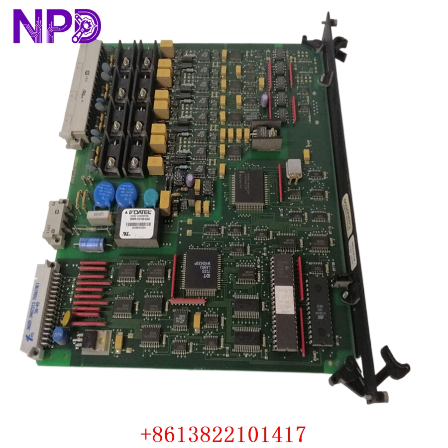
ALSTOM AS111-1
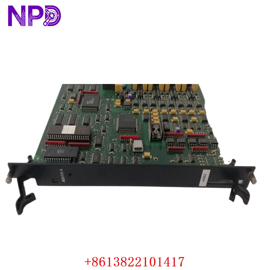
ALSTOM AS111-1
Applications
- Steam and Gas Turbine Control: Regulates fuel throttle valve positions, guide vane actuators, and hydraulic governor setpoints in high-capacity power stations.
- Process Valve Modulation: Interfaces with smart electro-pneumatic positioners to control fluid delivery, line pressure, and thermal flow rates in refineries.
- Continuous Combustion Systems: Integrates directly with furnace combustion loops, balancing fuel-to-air ratios through analog speed control outputs to industrial draft fans.
- Railway and Traction Systems: Deployed inside specific high-reliability ALSTOM traction power distribution frameworks and remote substations to guide auxiliary current loops.
Product Usage Instructions
- Pre-Installation Hardware Setup: Inspect the PCB for proper hardware revision compatibility tags. Ensure your backplane slot corresponds with the specific power requirements of the card revision, matching your target field bus terminal layout.
- Module Slotting and Mounting: Shut down power to the local ALSPA I/O subrack chassis section. Align the board card edges accurately within the upper and lower guide rails. Push the card fully into the chassis until the backend DIN connectors click firmly into the backplane, then lock the faceplate fasteners.
- Field Channel Termination: Route the 4-20mA loop wiring into the dedicated terminal block assembly (such as the UT129, UT150, or UT156 carrier interfaces). Maintain a common process 0V baseline loop references as specified, ensuring field shields are grounded at the cabinet wall.
- Software Configuration and Calibration: Access your ALSPA engineering workbench tool to assign the hardware address profile for the module. Configure the channel variables (0-20mA or 4-20mA loops) and apply the respective scaling constants before pushing the updated database to the primary controller CPU.
Frequently Asked Questions (Q&A)
- Q: Does the AS111-1 analog output module feature internal loop feedback monitoring?
A: Yes, the module incorporates an internal analog output feedback diagnostic system. It continuously cross-checks the physical output current values against the digital command parameters provided by the processor, instantly flagging deviations as channel faults.
- Q: What is the main structural distinction between the legacy AS111-1 card and the newer AS111-2 variant?
A: The primary variance centers on the process voltage tolerance, line protections, and grounding optimization designs. The AS111-2 features updated positive temperature coefficient (PTC) protection thresholds explicitly configured for stable, modern 24V DC process voltage networks.
- Q: Is external power required to energize the analog loop outputs of this module?
A: Yes, the analog output circuits rely on external process voltage distributions supplied via the terminal module blocks to sustain loop current propagation through field devices and actuator transceivers.
- Q: Can the AS111-1 board be safely hot-swapped while the active controller subrack is powered on?
A: It is strongly advised to isolate power to the subrack before extracting the module card. Live hot-swapping can introduce voltage transients into the shared digital data bus, resulting in execution dropouts or temporary communication loss across adjacent I/O modules.