Description
Product Overview
The Applied Materials 0100-20458 is a configurable chamber interlock PCB used in Applied Materials semiconductor processing equipment. Public spare-parts and repair references identify this part as a PVD/IMP Chamber Interlock PCB and as a configurable interlock assembly. It is also associated with chamber interface and interlock functions in AMAT process equipment.
The interlock board is part of the equipment safety and control architecture. Its job is to participate in monitoring and controlling permissive conditions so that equipment operations can proceed only when the required chamber, transfer, gas, or related conditions are satisfied.
For semiconductor equipment maintenance, the exact board revision and installed configuration are important. Different listings associate this part number with configurations or related part numbers such as 0130-20458, 0190-00285, 0100-00510 and other interlock assemblies, so replacement should be based on the complete part number, revision, connector arrangement, and equipment configuration rather than the base number alone.
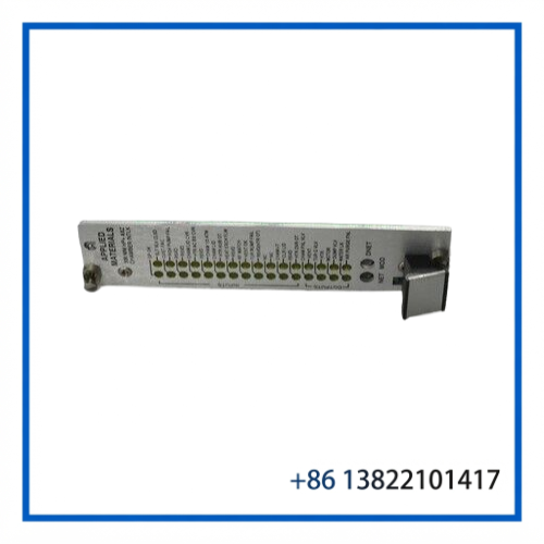
Key Features
- Applied Materials / AMAT semiconductor equipment spare part
- Configurable interlock PCB assembly
- Chamber interlock control and interface function
- Used in semiconductor process equipment architectures
- Associated with PVD/IMP chamber applications in public spare-parts listings
- Suitable as a maintenance spare when the installed configuration is confirmed
- Multiple revisions and associated configurations may exist
Technical Datasheet
| Parameter | Details |
|---|---|
| Manufacturer | Applied Materials |
| Part Number | 0100-20458 |
| Product Type | Configurable Chamber Interlock PCB |
| Application | Semiconductor processing equipment |
| Functional Category | Chamber / equipment interlock interface |
| Associated Description | PVD/IMP Chamber Interlock PCB |
| Configuration | Configurable |
| Related Part Numbers | 0130-20458 and other configuration-specific references may appear |
| Board Revision | Verify from the physical board |
| Input / Output Voltage | Verify from OEM equipment documentation |
| Communication Interface | Configuration-dependent / verify |
| Dimensions | Verify from physical board |
| Operating Temperature | Verify from equipment documentation |
Public listings consistently identify 0100-20458 as an interlock-related board, but I did not find an authoritative OEM datasheet that confirms detailed electrical ratings, connector pinouts, dimensions, or communication specifications. Those values should therefore be checked against the equipment manual or the installed board before replacement.
Functional Description
In an Applied Materials process tool, an interlock circuit provides a layer of equipment protection and operating permission.
The 0100-20458 board can be considered part of the control path that handles interlock conditions associated with the chamber or process module. Depending on the specific tool configuration, these conditions may include equipment status, chamber access, transfer conditions, process permissives, and other signals required before a sequence can continue.
A fault on an interlock board can therefore appear as more than a simple PCB failure. The equipment may report an interlock fault, refuse to start a sequence, prevent chamber operation, or stop a transfer-related operation.
One repair reference specifically identifies 0100-20458 as an AMAT 12-inch TxZ Gas Box Interlock Board, while other sources identify it as a PVD/IMP Chamber Interlock PCB. This suggests that the same base part number may be encountered in different AMAT equipment configurations, making configuration verification particularly important.
Typical Applications
The board may be encountered in Applied Materials semiconductor manufacturing equipment involving:
- PVD process modules
- IMP-related chamber systems
- Chamber interlock circuits
- Gas-box/interlock control assemblies
- Chamber interface systems
- Equipment safety and permissive circuits
- Legacy AMAT process-tool maintenance
It has also been listed in connection with HDPCVD and preclean/chamber interlock applications, so the equipment model should always be checked before ordering a replacement.
Installation & Configuration
Before installing the replacement board:
- Verify the complete part number
Confirm 0100-20458 and compare the board revision and configuration against the existing board. - Compare connectors and jumpers
Check connector positions, jumper settings, DIP-switch settings, and any configuration components before removal. - Record the original configuration
Take clear photographs of the original board before disconnecting it. This is especially useful for configurable interlock assemblies. - Use ESD protection
Handle the PCB using appropriate ESD precautions and avoid touching exposed electronic components. - Check the interlock wiring
Inspect harnesses, connectors, terminals, and external sensors before concluding that the PCB itself is defective. - Perform equipment-level verification
After installation, verify interlock status, chamber permissives, alarms, and relevant equipment sequences according to the applicable AMAT service procedure.
Because an interlock circuit can directly affect equipment safety, installation and testing should be performed by qualified semiconductor-equipment personnel.
Maintenance & Inspection
For a stored spare, periodic inspection should include:
- PCB surface contamination
- Corrosion or oxidation
- Connector condition
- Bent or damaged pins
- Burn marks or overheated components
- Cracked solder joints
- Damaged terminal blocks
- Missing jumpers or configuration components
- Part-number and revision label condition
For an installed board, pay particular attention to intermittent interlock alarms. A loose connector or damaged harness can produce symptoms that resemble a failed interlock PCB.
Troubleshooting Reference
| Symptom | Possible Cause |
|---|---|
| Chamber interlock remains active | Sensor, wiring, connector, or PCB fault |
| Equipment cannot start process | Required permissive condition not satisfied |
| Intermittent interlock alarm | Loose connector, damaged harness, contamination, or unstable signal |
| Transfer sequence inhibited | Transfer/chamber interlock condition not satisfied |
| Board replacement does not clear alarm | Incorrect revision/configuration or external interlock fault |
The PCB should not automatically be identified as the failed component simply because an interlock alarm is present. The associated sensors, wiring, power supply, and upstream/downstream control circuits should also be checked.
Replacement Compatibility
The safest replacement strategy is exact part-number matching.
Public listings show several related numbers and configurations around 0100-20458, including 0130-20458 and other AMAT interlock-related assemblies. These should not be treated as direct substitutes without confirming the equipment model, board revision, connector arrangement, and configuration.
For procurement, provide the following information whenever possible:
- Applied Materials equipment model
- Existing board part number
- Board revision
- Photos of front and rear sides
- Connector configuration
- Any secondary or assembly number
- Existing equipment alarm information
Product Identification
Manufacturer: Applied Materials
Part Number: 0100-20458
Description: HP+ AXZ Chamber Interlock / Configurable Interlock PCB
Application: Applied Materials semiconductor processing equipment
Category: Semiconductor Equipment Control / Interlock PCB
Recommended eBay SEO Title
Applied Materials 0100-20458 HP+ AXZ Chamber Interlock PCB Configurable Board
Short Chinese Title
Applied Materials 0100-20458 | HP+ AXZ腔体互锁PCB板