Description
🔹 Product Overview
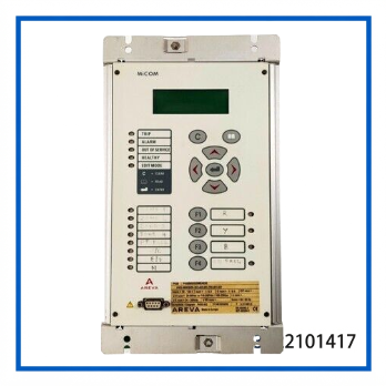
The AREVA MiCOM P430 P4309893020MEAE00 is a numerical protection relay designed for electrical power-system protection, monitoring, and control applications. The MiCOM P430 family belongs to the multifunction protection relay platform and is commonly used where programmable protection functions, measurement, event handling, and communication are required.
The relay can be integrated into medium- and high-voltage electrical systems as part of a coordinated protection scheme. Depending on the exact hardware and software configuration, available functions may include overcurrent, earth-fault, voltage, frequency, thermal, circuit-breaker supervision, programmable logic, and disturbance/event recording functions.
For replacement projects, the complete ordering code P4309893020MEAE00 should be matched against the existing relay’s hardware configuration, auxiliary supply, I/O arrangement, communication options, firmware, and protection settings before installation.
🔹 Key Features
- Numerical protection relay for industrial and power-system applications
- MiCOM P430 multifunction protection platform
- Programmable protection and control functions
- Phase and residual current protection functions depending on configuration
- Voltage and frequency protection functions depending on configuration
- Circuit-breaker monitoring and protection logic
- Configurable binary inputs and relay outputs
- Event and fault recording capability
- Suitable for integration with substation and industrial protection systems
- Designed for maintenance and replacement of legacy MiCOM protection equipment
🔹 Technical Datasheet
| Parameter | Specification |
|---|---|
| Brand | AREVA |
| Model | P430 |
| Part Number | P4309893020MEAE00 |
| Series | MiCOM P430 |
| Product Name | Motor / Power System Protection Relay |
| Product Type | Numerical Multifunction Protection Relay |
| Protection Functions | Configuration-dependent; overcurrent, earth fault, voltage, frequency and related functions |
| Control & Monitoring | Programmable inputs, outputs, logic and circuit-breaker monitoring |
| Recording Functions | Event, fault and disturbance recording depending on configuration |
| Application | Motor, feeder and industrial/power-system protection applications |
🔹 Protection and Monitoring Functions
The MiCOM P430 platform provides a multifunction numerical protection architecture rather than a single-purpose protective element. Depending on the selected configuration, protection schemes can incorporate ANSI functions such as 50/51 phase overcurrent, 50N/51N earth fault, voltage protection, frequency protection, thermal protection, circuit-breaker failure and related monitoring functions.
This makes the relay suitable for protection schemes where several protective elements must be coordinated within one programmable device.
🔹 System Integration
A typical installation can be organized as:
CT / VT Signals → MiCOM P430 → Protection Logic → Trip / Alarm Outputs → Circuit Breaker
The relay can receive measured electrical quantities from current and voltage transformers and use these measurements for protection decisions. Binary inputs can be used for breaker status, interlocking, external trip/blocking signals, or other application-specific signals.
Before commissioning, verify the complete terminal assignment because I/O availability and functions can vary with the ordered configuration.
🔹 Installation & Commissioning
- Confirm the complete part number and relay hardware configuration.
- Compare the replacement unit with the existing relay before removing the original.
- Verify CT and VT ratios, polarity, phase sequence, and wiring.
- Check the auxiliary supply voltage and terminal assignments.
- Confirm binary input and output assignments.
- Load or verify the required protection settings.
- Check communication parameters where a station or supervisory network is used.
- Perform secondary injection and functional protection testing.
- Test trip, alarm, breaker supervision, and interlocking circuits.
- Record the final settings and commissioning results.
🔹 Troubleshooting Guide
Relay does not power up:
Check the auxiliary supply, fuse, wiring, polarity, and terminal connections.
Incorrect current or voltage measurement:
Check CT/VT ratios, phase sequence, polarity, wiring, and configured measurement parameters.
Unexpected protection trip:
Review the active protection element, pickup value, time delay, fault record, and measured quantities before changing settings.
Breaker status is incorrect:
Check binary input wiring and the configured input logic against the actual breaker auxiliary contacts.
Communication failure:
Verify the communication option installed in the relay, addressing, baud rate, parity, wiring, and protocol configuration.
Replacement relay behaves differently:
Compare hardware version, firmware, configuration options, protection settings, and I/O assignments rather than assuming that two P430 units are electrically identical.
🔹 Maintenance
For long-term service, periodically inspect terminal connections, auxiliary power quality, relay indications, protection settings, communication status, and recorded events.
Protection settings should be backed up before maintenance work. Functional testing should be performed according to the site’s protection-maintenance procedures, especially for critical motor and feeder circuits.
Because the P430 is a legacy protection platform, maintaining a tested spare can reduce downtime when an installed relay develops a hardware or display problem.
🔹 Replacement Considerations
The ordering code P4309893020MEAE00 is important for replacement identification. A replacement should not be selected only by the generic “P430” model designation.
Before purchasing or installing a spare, compare:
- Complete ordering code
- Auxiliary supply
- CT/VT input arrangement
- Binary inputs and relay outputs
- Communication interfaces
- Protection-function configuration
- Firmware compatibility
- Existing setting files
- Panel cutout and terminal arrangement
- Application-specific logic
This is particularly important when replacing a relay in an operating protection system.
🔹 Frequently Asked Questions
Q1: What is the AREVA MiCOM P430 used for?
It is a numerical multifunction protection relay used for electrical protection, monitoring, and control applications.
Q2: Is P430 a motor-only protection relay?
The P430 platform can be applied to several power-system protection applications. The exact application depends on the configured protection functions and ordering code.
Q3: Does P430 support overcurrent protection?
Yes, the MiCOM protection platform includes overcurrent protection functions, with the exact implementation dependent on the relay configuration.
Q4: Can the P430 monitor circuit-breaker status?
Circuit-breaker monitoring and associated control/protection functions are available within the MiCOM platform, subject to configuration.
Q5: Can this unit directly replace another P430?
Only after confirming the complete ordering code, hardware, firmware, I/O, communication options, and protection settings.
Q6: Is the P430 suitable for legacy system maintenance?
Yes. It can be valuable as a replacement or spare for existing installations using the MiCOM P430 platform.
Q7: What should be checked before commissioning?
CT/VT wiring, auxiliary supply, I/O assignment, protection settings, communication parameters, trip circuits, and interlocking logic should all be verified.
Q8: Can protection settings be transferred from another relay?
Settings may be reusable when the hardware and configuration are compatible, but they should always be reviewed and validated before commissioning.
🔹 10 Related MiCOM Protection Models
- MiCOM P130C
- MiCOM P132
- MiCOM P139
- MiCOM P241
- MiCOM P242
- MiCOM P243
- MiCOM P430C
- MiCOM P432
- MiCOM P433
- MiCOM P437
🔹 Product Summary
The AREVA MiCOM P430 P4309893020MEAE00 is a configurable numerical protection relay for industrial and electrical power-system applications. Its multifunction architecture supports protection, monitoring, control, event handling, and system integration.
For maintenance and replacement projects, matching the complete P4309893020MEAE00 configuration is essential to ensure compatibility with the installed protection scheme, wiring, settings, and communication architecture.