
Description
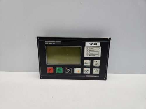
The AUTO-MASKIN DCU 305 A R2 is a rugged, microprocessor-based engine control unit designed specifically for the control and monitoring of diesel engines used in marine and industrial applications. This controller provides essential functions including automatic engine start/stop sequences, comprehensive engine protection, and local instrumentation. The R2 version represents a mature, field-proven hardware iteration known for its high reliability in harsh environments.
⚙️ Technical Specifications
- Dimensions: 144 mm x 144 mm x 115 mm (Standard panel cutout)
- Weight: 0.8 kg
- Country of Origin: Norway
- Power Input: 12V DC or 24V DC (Auto-sensing)
- Operating Temperature: -20°C to +70°C
- Protection Class: IP54 (Front panel)
- Display: Graphical LCD with adjustable backlight
🏗️ Application Areas
- Marine Propulsion Engines
- Emergency Generator Sets
- Fire Pump Controllers
- Industrial Compressor Drives
- Auxiliary Engine Monitoring
📖 Product Usage Instructions
The DCU 305 should be panel-mounted in an environment protected from extreme direct water spray. Connect all sensor inputs—such as oil pressure, coolant temperature, and magnetic pickup (speed)—to the clearly marked terminal blocks on the rear. Ensure the system is connected to a stable battery supply and that a dedicated ground cable is utilized to minimize electrical interference from engine starters.
🌐 Communication Configuration Steps
- IP Address: For models equipped with an Ethernet interface, use the Auto-Maskin configuration software via the service port to set a static IP, Subnet Mask, and Gateway.
- Station Number: Navigate to “Communication Settings” on the front panel menu to assign a unique Modbus Slave ID (e.g., 1–247) for integration with a VMS or SCADA.
- Baud Rate: Configure the serial port speed (typically 9600, 19200, or 38400 bps) to match your master controller’s data requirements.
⚡ Power-Up Debugging Flow
- Verify correct battery voltage (12V or 24V) at the power terminals.
- Ensure the “Emergency Stop” button is in the released position.
- Apply power; the unit will perform an automatic self-test of the LCD and LED indicators.
- If “Sensor Fault” appears on startup, check the wiring and resistance of the connected temperature and pressure transducers.
- Once the display shows the main dashboard, verify the “Ready” status indicator.
✅ Initial Run Checklist
- Perform a “Lamp Test” from the menu to ensure all status LEDs are functional.
- Verify speed readings match actual engine RPM during the first crank attempt.
- Simulate a high-temperature alarm to ensure the unit triggers the appropriate shutdown/alarm output.
- Confirm that the engine start sequence follows the configured crank/rest cycle.
- Save the full configuration file (including setpoints and thresholds) to a backup device using the service software.
❓ Frequently Asked Questions (Q&A)
Q: What is the benefit of the “R2” revision? A: The R2 version includes enhanced hardware resilience against voltage spikes and improved processor speed for faster reaction times during engine start/stop sequences compared to the original design.
Q: Can I use this with any type of engine sensor? A: The DCU 305 supports most standard industrial sensors, but input types (4-20mA, resistive, or switch contact) must be configured correctly in the software menu before operation.
Q: How do I clear an alarm history? A: Navigate to the “Alarm Log” menu using the front panel buttons. Select “Clear Log” to reset the history (note: this should only be done after documenting the error codes for maintenance records).
Q: Is it possible to remotely start the engine? A: Yes, the DCU 305 has remote start/stop digital inputs designed for integration with external building management or bridge control systems.